Introduction
The world is becoming more digitalized than ever before. The workload of data centers has tripled since 2015 [1]. Despite huge progress in thermal management, traditional air-based cooling technology still represents a critical factor that significantly impacts data center operating costs and the environment. Depending on the size and operating conditions of a data center, a significant portion of the total energy consumption (up to 55%) is used to cool the servers. Therefore, the implementation of greener cooling technologies that can re-use the heat generated by the servers for other purposes (i.e. room heating, power generation, etc.) is becoming more and more attractive. The novel passive two-phase cooling technology, presented in this article, offers not only a very efficient way to manage the heat load of the servers, with a substantially higher heat flux limit versus traditional technology but also offers a feasible and economically viable way to re-use that energy.
Thermal and Fluidic Phenomena in the Operation of a Single Loop Thermosyphon
A single loop thermosyphon is composed of four elements:
- The evaporator: where the absorbed latent heat changes the working fluid’s phase from liquid to a liquid-vapor mixture
- The condenser: where the latent heat rejection changes the vapor back to the liquid phase
- The riser: which transports the liquid-vapor mixture upward from the evaporator to the condenser
- The downcomer: which carries the liquid downward from the condenser to the evaporator
A schematic of a single loop thermosyphon is reported in Figure 1. The condenser must be placed above the evaporator to favor buoyantly driven passive flow circulation, and due to the small channel sizes, slug and annular flows are the main flow patterns occurring during the operation of a thermosyphon [2, 3].
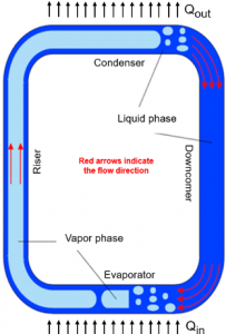
As general design guidelines for electronics cooling applications, it is important to ensure a subcooled liquid at the evaporator inlet and a sufficiently low vapor quality at the evaporator outlet to avoid four phenomena related to the two-phase flow in micro-channels and thermosyphons in particular:
- Dry-out: the vapor phase, with its poor heat transfer characteristics, may blanket the wall when the vapor quality approaches one. Therefore it is imperative to have a fully wetting flow at the evaporator outlet. Generally, the thermosyphon can safely operate with vapor quality in the range of between 0.1 and 0.5. Note: vapor quality is defined as the ratio between the mass of vapor flow divided by the total mass flow rate (liquid and vapor)
- Instabilities: a subcooled liquid at the evaporator inlet eliminates pressure-related instabilities in micro-channels and Ledinegg’s instability in a thermosyphon loop [4]
- Backflow: at high heat loads, the rapid growth of vapor may push the flow backward, triggering flow instabilities and decreasing thermal performance. The subcooled liquid prevents this from occurring, but it must be coupled with careful design of the inlet manifold and flow distribution in the evaporator
- Gravity-driven flow: a single loop thermosyphon has two working regimes. The gravity-dominant regime occurs when the buoyancy in the riser is the primary force, up to when the heat duty creates sufficient vapor qualities to change to friction-dominant flow. A thermosyphon should be designed to operate in a gravity-dominant regime as the mass flow rate increases with the heat load, and the subcooled liquid at the evaporator inlet serves this purpose [5]
Subcooling at the inlet and the latent heat transfer both affect the thermal performance. They are related to the heat load through the energy balance on the working fluid:
where Q (W) is the total heat load (comprised of subcooled and saturated heat loads), (kg/s) is the coolant mass flow rate, cp (J/kg/K) is the specific heat at constant pressure, ΔTsub (K) is the subcooling at the evaporator inlet, Δhlv (J/kg) is the latent heat of vaporization, and xout (-) is the outlet vapor quality. To minimize the total thermal resistance, the subcooled heat load needs to be minimized, while the saturated heat load needs to be maximized. Therefore, it is paramount to find the right trade-off together with the design guidelines reported above.
Test Results with a Single Loop Thermosyphon Prototype
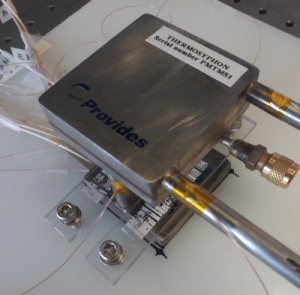
A newly designed thermosyphon prototype suitable for server-level cooling is depicted in Figure 2; Figure 3 illustrates a schematic diagram including the main components and measurements. The main components of the test setup are the following:
- A low-height water-cooled thermosyphon designed for cooling 2-U servers. The evaporator was directly attached to the heat source via a highly conductive thermal grease (Thermal Grizzly Kryonaut: thermal resistance of 0.0032 K/W and thermal conductivity of 12.5 W/m/K)
- A pseudo-chip with a footprint area of 4 x 4 cm2 designed with four cartridge heaters in parallel, that were located in a copper block. Four calibrated K-type thermocouples (accuracy of ± 0.25 °C were used to measure the mean heater temperature. The junction (evaporator base) temperature was evaluated from the mean heater temperature and a 1-D heat conduction calculation accounted for the thermal resistance through the copper and thermal interface material. Another K-type thermocouple was attached on the adiabatic section of the riser to measure the saturation temperature
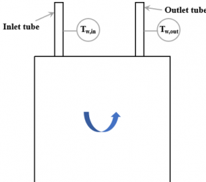
- A thermal bath circulated cold water at a given temperature and flow rate on the secondary side of the thermosyphon. Its flow rate was indirectly determined from an energy balance using the water’s temperature rise, with K-type thermocouples attached on the inlet and outlet tubes, and imposed heat load, assuming negligible heat loss to the ambient
- A customized charging station (not shown here) was designed and fabricated to fill the thermosyphon with R1234ze up to the desired charge
- An electrical circuit (a power supply, four cartridge heaters and a shunt resistor) were used to power the pseudo-chip and to accurately measure the heat delivered to the refrigerant flow (maximum value of 333 W, but thermosyphon tests were executed up to about 200 W)
- A data acquisition system was coupled to LabView to control the operating conditions, monitor the thermal performance over time, and record the measured parameters (i.e. temperatures, power, etc.), which were post-processed separately
(a) 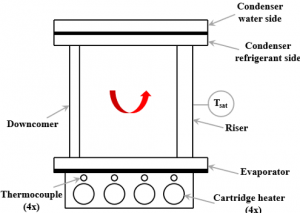
Figure 3: Schematic diagram of the thermosyphon: (a) front view, where the red arrow indicates the refrigerant flow direction; (b) top view showing the condenser secondary side and water flow direction.
Table 1 reports the external dimensions of the thermosyphon (the internal features are confidential).
| Table 1: Dimensions of the thermosyphon. | |
| PARAMETER | VALUE |
| Evaporator length, width and depth | 60 x 60 x 9.50 (mm) |
| Riser height | 42 (mm) |
| Riser external diameter | 10 (mm) |
| Condenser length, width and depth | 60 x 60 x 18.50 (mm) |
| Downcomer height | 42 (mm) |
| Downcomer external diameter | 8 (mm) |
| Total thermosyphon height | 70 (mm) |
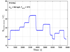
The cooling capabilities of the server-level thermosyphon were evaluated under transient and steady-state conditions. In particular, the results presented in this section refer to a secondary side water mass flow rate in the condenser of 364 kg/h and water inlet temperature of 15°C and a maximum heat load of 200 W (corresponding to a footprint heat flux of 16.3 W/cm2) using the refrigerant R1234ze as the working fluid. This is a very promising refrigerant for electronics cooling applications due to its negligible environmental impact (i.e. Global Warming Potential is less than 1) [6].
(a)
(b)
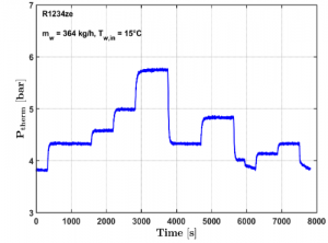
Figures 4(a) and 4(b) depict the server-level thermosyphon thermal performance with a maximum heater temperature of 46°C at the maximum power of 200 W, while the corresponding system pressure was measured to be only 5.8 bar. No temperature overshoots or pressure fluctuations were observed, meaning that the thermosyphon offered stable cooling over a wide range of changing heat loads. Also, rapid thermal responses and smooth transients were observed during the start-up operations at the times of 300 s (0-100 W) and 6,300 s (0-70 W). This is due to the fact that passive two-phase flow instabilities were minimized by ensuring the right level of liquid in the downcomer in order to prevent condenser flooding and to balance the total pressure drop in the loop (the latter was important to avoid intermittent flow in the evaporator which may induce partial dry-out). The temperature and pressure measurements followed similar trends and they both increased with the heat load, due to the higher vapor formation rate in the closed system.
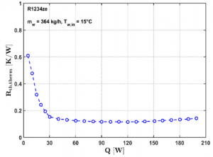
Figure 5 shows the total thermal resistance as a function of the heat load. Conduction thermal resistance played a negligible role in the heat transfer as the gravity-driven two-phase flow circulation was triggered at very low heat loads (3-5 W). Overall, the total thermal resistance decreased with increasing heat load due to the enhancement of the boiling process due to the higher refrigerant mass flow rate, vapor quality and heat flux. The change in the thermal resistance slope at about 30 W coincided with the enhanced heat transfer performance when changing from slug-plug flow to annular flow in the evaporator. The minimum value of thermal resistance was about 0.113 K/W when the heat load was 120 W.
Calculation of Working Fluid’s Mass Flow Rate
The thermosyphon’s working fluid mass flow rate could not be directly obtained through single-phase pressure drop measurements [7] or energy balance calculations [8] due to the small form factor of the system. A commercial code [9, 10] was then used to estimate the thermosyphon mass flow rates. Specifically, the inputs needed to solve for the mass flow rates were the full geometry, fluids (R1234ze and water), operating conditions, and measured thermal resistance curve (see Figure 5). This in-house simulator has already been shown to be accurate in validations against many independent thermosyphon databases [8, 11-14].
Figure 6 depicts the simulated thermosyphon mass flow rates as a function of the heat load. As expected, the mass flow rate increased with the heat load due to the larger system driving force (buoyancy in the riser), which was able to overcome the total pressure drop in the thermosyphon (evaporator, riser, downcomer, and condenser). The server-level thermosyphon was seen to be operating in the desired gravity-dominant regime [5].
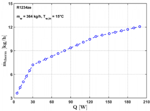
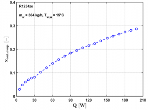
Figure 7 presents the corresponding outlet vapor quality as a function of the heat load, calculated through an energy balance across the evaporator under the assumption of negligible heat loss to ambient (reasonable as the thermosyphon is fully insulated). The highest exit vapor quality was 29%, which was well below the critical value of 55% at the onset of dry-out (based on the simulated threshold value from the code).
Two-Phase Cooling Implementation
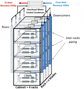
The envisioned cooling technology applied to an entire server rack is presented in Figure 8. In particular, this cooling technology operates with numerous server-level thermosyphons in order to dissipate the heat produced by the large heat sources (i.e. microprocessors, memories, etc.) into the two-phase micro-evaporators and out through the two-phase micro-condensers [8]. Then, the heat is transferred to rack-level thermosyphons designed with a common overhead compact condenser, which dissipates the total heat from the server rack (20-100 kW or more) into the data center’s water cooling loop [15]. The low power components (i.e. motherboards, lighting, etc.) can be air-cooled and the warm air is rejected into the room.
Conclusions
The present paper describes and presents test results for an innovative passive two-phase cooling technology for next-generation high-performance computers, which provides higher energy efficiency compared to air- and liquid-cooling technologies deployed today. The experimental study presented in this article was mainly focused on the thermal performance characterization of a low-height thermosyphon to be used in 2-U servers. Experimental results demonstrated very good heat transfer performance and stable cooling capabilities over a wide range of heat loads. The present cooling technology enables high heat transfer performance, low noise level, scalability towards higher heat dissipations and improved reliability while using an environmentally friendly refrigerant (R1234ze) as the working fluid.
Acknowledgments
This work is carried out as part of the Eurostars Project (PCOOLDATA) that is co-funded by Eureka member countries and the European Union Horizon 2020 Framework Programme, which are gratefully acknowledged for their support. Also, the authors would like to acknowledge Dr. Jackson Braz Marcinichen (JJ Cooling Innovation Sàrl) for contributing on the thermosyphon design and advising on the implementation of the proposed technology.
References
[1] J. Dulac, T. Abergel, C. Delmastro, Data centres and Data Transmission Networks. International Energy Agency report, online webpage: https://www.iea.org/reports/tracking-buildings/data-centres-and-data-transmission-networks, 2019.
[2] C.L. Ong, J.R. Thome, Macro-to-microchannel transition in two-phase flow: part 1 – two-phase flow patterns and film thickness measurements. Experimental Thermal and Fluid Science, 2011.
[3] J.W. Coleman, S. Garimella, Two-phase flow regimes in round, square and rectangular tubes during condensation of refrigerant R134a. Internal Journal of Refrigeration, 2003.
[4] L.C. Ruspini, C.P. Marcel, A. Clausse, Two-phase flow instabilities: a review. International Journal of Heat and Mass Transfer, 2014.
[5] H. Bielinski, J. Mikielewicz, Natural circulation in single and two-phase thermosyphon loop with conventional tubes and minichannels. Heat transfer-mathematical modeling, numerical methods and information technology, 2011.
[6] ESRL Chemical Sciences Division, Scientific assessment of ozone depletion: 2018. Online webpage: https://www.esrl.noaa.gov/csd/assessments/ozone/2018/downloads/, Ozone, 2018.
[7] T. Salamon, R.L. Amalfi, N. Lamaison, J.B. Marcinichen, J.R. Thome, Two-Phase Liquid Cooling System for Electronics, Part 1: Pump-Driven Loop. Intersociety Conference on Thermal and Thermomechanical Phenomena in Electronic Systems (ITHERM), 2017.
[8] C.L. Ong, R.L. Amalfi, N. Lamaison, J.B. Marcinichen, J.R. Thome, Two-Phase Mini-Thermosyphon for Cooling of Datacenters: Experiments, Modeling and Simulations. International Technical Conference and Exhibition on Packaging and Integration of Electronic and Photonic Microsystems (InterPACK), 2017.
[9] J.B. Marcinichen, R.L. Amalfi, N. Lamaison, T. Salamon, J.R. Thome, Two-Phase Liquid Cooling System for Electronics, Part 4: Modeling and Simulations. Intersociety Conference on Thermal and Thermomechanical Phenomena in Electronic Systems (ITHERM), 2017.
[10] N. Lamaison, C.L. Ong, J.B. Marcinichen, J.R. Thome, Two-Phase Mini-Thermosyphon Electronics Cooling: Dynamic Modeling, Experimental Validation and Application to 2U Servers. Applied Thermal Engineering, 2017.
[11] C.L. Ong, N. Lamaison, J.B. Marcinichen, J.R. Thome, Two-Phase Mini-Thermosyphon Electronics Cooling, Part 1: Experimental Investigation. Intersociety Conference on Thermal and Thermomechanical Phenomena in Electronic Systems (ITHERM), 2016.
[12] R.L. Amalfi, T. Salamon, N. Lamaison, J.B. Marcinichen, J.R. Thome, Two-Phase Liquid Cooling System for Electronics, Part 2: Air-Cooled Condenser. Intersociety Conference on Thermal and Thermomechanical Phenomena in Electronic Systems (ITHERM), 2017.
[13] R.L. Amalfi, T. Salamon, N. Lamaison, J.B. Marcinichen, J.R. Thome, Two-Phase Liquid Cooling System for Electronics, Part 3: Ultra-Compact Liquid-Cooled Condenser. Intersociety Conference on Thermal and Thermomechanical Phenomena in Electronic Systems (ITHERM), 2017.
[14] F. Cataldo, J.R. Thome, Experimental Evaluation of the Thermal Performances of a Thermosyphon Cooling System Rejecting Heat by Natural and Forced Convection. Applied Thermal Engineering, 2017.
[15] R.L. Amalfi, F. Cataldo, J.R. Thome, An Optimization Algorithm to Design Compact Plate Heat Exchangers for Waste Heat Recovery Applications in High Power Datacenter Racks. Intersociety Conference on Thermal and Thermomechanical Phenomena in Electronic Systems (ITHERM), 2019.
[16] N. Lamaison, J.B. Marcinichen, J.R. Thome, Efficiency Improvements of a Thermal Power Plant by Making Use of the Waste Heat of Large Datacenters Using Two-Phase On-Chip Cooling. Proceedings of the World Engineer’s Convention, 2011.
About the Authors
Raffaele Luca Amalfi is a Lead Researcher at Nokia Bell Labs New Jersey, where he performs cutting-edge research in the field of thermal management of high-performance communications and computing systems across multiple scales. He is the Principal Investigator on behalf of Nokia of America Corporation and Bell Labs for the Eurostars Project PCOOLDATA focused on the development of innovative cooling solutions for data centers. Since 2016 he worked as Scientific Collaborator and Lab Manager at the Swiss Federal Institute of Technology of Lausanne (EPFL), at the Heat and Mass Transfer Lab, in Switzerland. In 2015 he joined Alcatel-Lucent Bell Labs in New Jersey, where he performed disruptive research on hybrid cooling technologies for telecom equipment. In 2012 he joined IBM Research Lab in Switzerland where he developed a novel cooling system for high-power electronics. He has received a Ph.D. in Energy Engineering from EPFL and he has authored more than 30 scientific publications.
Filippo Cataldo is a Senior Engineer at Provides Metalmeccanica S.r.l. in Italy working on micro-cooling solutions. He is the supervisor of the lab testing and design of micro-channels evaporators, condensers and passive systems, such as thermosyphons and heat pipes. He is the lead engineer for the E.U. funded projects (Clean Sky and PCOOLDATA). He has received a Ph.D. from University of Naples Federico II in 2015, where he gained extensive experience in experimental design/analysis, numerical modelling, energy conversion, and optimization of Organic Rankine Cycles. In the same year, he joined the Heat and Mass Transfer Lab (LTCM) at EPFL as a scientific collaborator. He conducted research in design, installation, and testing of a novel, completely passive, cooling system for a transistor module. He has authored more than 10 scientific publications and he serves as a reviewer for journals and conferences papers on the topics of energy conversion, heat transfer and thermal management.
John Richard Thome is currently Professor-Emeritus of Heat and Mass Transfer at the Swiss Federal Institute of Technology of Lausanne (EPFL), Switzerland, and he was Full Professor from 1998 to 2018. In 2014, he co-founded a consulting company, JJ Cooling Innovation Sàrl, in Lausanne. He is the author of five books and more than 250 journal papers on two-phase flow heat transfer and micro-two-phase cooling systems for electronics cooling. He received the Nusselt-Reynolds Prize in 2017, the ASME Journal of Heat Transfer Best Paper Award in 1998, the United Kingdom’s Institute of Refrigeration J.E. Hall Gold Medal in 2008, the ASME Heat Transfer Memorial Award in 2010, the IEEE Richard Chu ITHERM Award in 2019 and the ASME Allan Krause Thermal Packaging Medal at InterPACK 2019. He obtained his Ph.D. at Oxford University and he founded the Virtual International Research Institute of Two-Phase Flow and Heat Transfer to promote research collaborations and education.
