Authored by Ross Wilcoxon and Genevieve Martin Associate Technical Editors for Electronics Cooling
For a number of reasons, including cost, simplicity, power consumption, noise, etc., natural convection is the preferred approach for cooling electronic systems. However, it is often the case that natural convection is simply not sufficient to remove dissipated power while meeting other system requirements such as size. Therefore, cooling fans are commonly used to increase cooling capacity to achieve an adequate design. This series of two articles provides an overview of the basics of effectively integrating cooling fans into a system and understanding other impacts of the use of fans. This first article focuses on how the use of fans impacts the cooling system design and how to determine the flow rate that a fan can produce in a specific application.
Before describing how to design a fan-cooled system for electronics, it is useful to first ask the question ‘why do fans improve cooling?’. While the benefits of a fan to improve cooling may seem obvious, a clear understanding of the physical mechanisms by which flow rate impacts thermal resistance is critical to developing effective designs.
To begin, convection heat transfer (Q), from a solid surface to a fluid, is described with the equation Q = h*A*(Tfluid – Tsurface), where T is temperature, A is the surface area in contact with the fluid, and h is the convection coefficient. In laminar flow, the coefficient is constant, regardless of flow rate. At higher velocities, the flow becomes turbulent and the heat transfer coefficient increases with velocity. While the surface temperature of a heat sink may be approximately uniform, the fluid temperature increases as it absorbs energy, with the fluid temperature at any point in the system defined as Tfluid = ṁ * cp / Q’ + Tinlet, where ṁ is the mass flow rate of coolant, cp is the specific heat of the coolant, Q’ is the heat absorbed by the coolant to that point in the system, and Tinlet is the temperature of the coolant when it enters the system. A larger flow rate can potentially affect heat transfer in two different ways: 1) by increasing the convection coefficient, which decreases the convective thermal resistance 1/hA, and 2) by reducing how much the fluid temperature increases as it flows through the system. This effectively adds an additional thermal resistance, which may be referred to as the advective thermal resistance, that can be approximated as 1/(2ṁcp)*
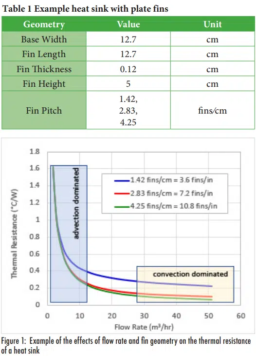
To illustrate how these two effects can influence the overall thermal resistance in a forced cooling application, the thermal resistances for parallel plate heat sinks with different flow rates were estimated using the approach described by Simons [1] for air cooling a heat sink dissipating 100W with the geometries shown in Table 1. Thermal resistances for different heat sinks and different flow rates are shown in Figure 1.
For this specific heat sink configuration, when the flowrate is less than ~5-10 m3/hr, the thermal resistance is dominated by the flow rate, i.e., advection thermal resistance. In this flow rate regime, there will be little to no benefit of changing the fin design. At the other extreme, above ~30 m3/hr, the benefits of increasing flow rate on the overall thermal resistance become quite small. Instead, the thermal resistance is dominated by the convection thermal resistance, which is decreased by increasing the heat transfer area by adding more fins. As described later in this article, the design of an air-cooled system typically begins by determining what flow rate corresponds to a target temperature rise for the cooling air and then determining fan and heat sink designs that are suitable for that flow.
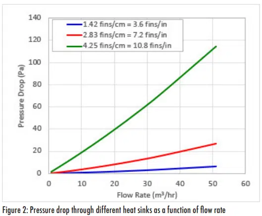
In order to improve a fan cooled system, it is important that the designers know where they are on the flow rate / thermal resistance curve. If a design is in the advection-dominated regime, increasing the size or number of fins will have minimal benefit; more flow is needed. In contrast, if a system is operating in the convection-dominated regime, there is little to be gained by increasing the flow rate. Instead, the heat sink resistance needs to be reduced, typically by increasing the number of fins. Figure 2 illustrates a typical result of modifying a heat sink to reduce its thermal resistance: the pressure drop through the heat sink increases. The pressure drop was calculated for the same three heat sink configurations shown in Table 1, using the approach described in Ref. [2]. In this case, the larger number of fins in the same space reduces the flow area, which directly increases the flow velocity and subsequently increases pressure drop.
Thus, both the thermal and pressure drop characteristics of a heat sink can be influenced by the flow rate generated by a fan. While the previous figures and discussion apply to the thermal/ fluid effects in a heat sink, the behaviors also apply to the overall thermal design of a system, in that the design generally requires a balance between reducing thermal resistance without excessively increasing pressure drop. The next section discusses the flow rate and pressure head generated by a fan and how system and fan characteristics are combined to determine the resulting system flow rate.
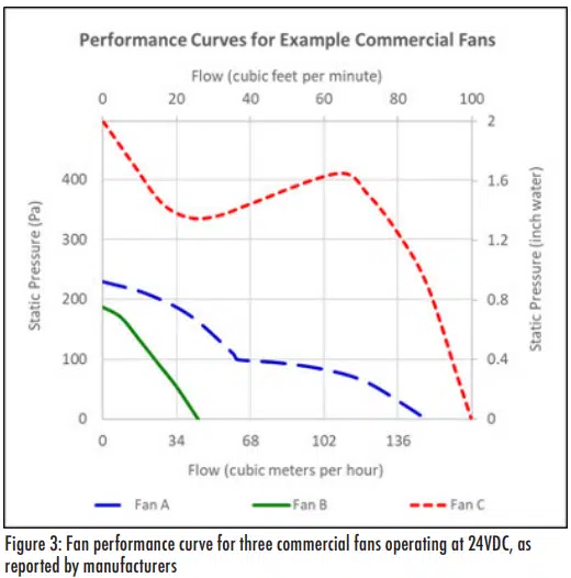
The pressure head generated by a fan as a function of the flow rate it generates are generally described in terms of fan curves; a few examples of which are shown in Figure 3. The different fans referenced in this plot all operate with the same 24VDC input power, but their physical geometries, expected use cases, price, noise, etc. are quite different.
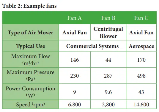
In addition to fan curves, manufacturers also generally provide characteristic data to help users understand their performance. Table 2 lists manufacturer-reported operating characteristics for the three air movers associated with the curves shown in Figure 3.
The quantified flow and pressure head parameters correspond to the extreme conditions (maximum flow is for zero pressure head, maximum pressure head is for zero flow rate), rather than actual use conditions in which the fan must generate both pressure head as well as flow. Thus, the actual operating point for a fan must be determined by comparing the fan curve to the system curve (also called system resistance curve).
The pressure drop that occurs when fluid flows through a heat sink, or any system, is a function of the flow velocity. If flow is completely laminar, the pressure drop is proportional to the square of the flow velocity; in completely turbulent flow, the pressure drop is proportional to the velocity. Actual flow through a system, which may include duct flow, turns, expansions, contractions, screens, etc., generally consists of regions of laminar and turbulent flow. As long as the flow of air is incompressible, local average velocities are proportional to the volumetric flow rate through a system and the pressure drop as a function of the volumetric flow rate, V, generally follows the equation ΔP = C*Vn , where C is a constant and the exponent, n, is between 1 and 2. The specific values of C and n depend on the system. This relationship for pressure drop as a function of flow rate is referred to as the system curve and must be determined through testing, simulations, or flow resistance analysis.
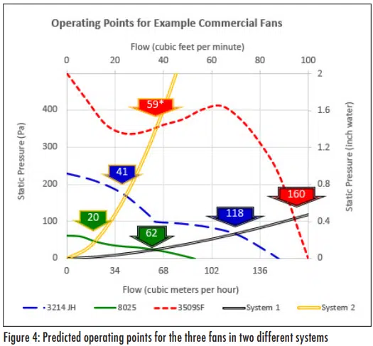
The flowrate in a fan-driven system is determined by superimposing the system curve (pressure drop as a function of flow through the system) and the fan curve (pressure head generated by the fan as a function of the flow rate it generates). The intersection of these two curves is known as the operating point. Figure 4 shows nominal operating points for the three fan curves shown previously for two system curves selected to represent low and
high pressure drop systems*. The block arrows in the plot indicate predicted operating points for each combination of fan and system curve, with the numbers in the block arrows indicating the flow rate for each operating point.
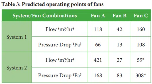
Table 3 summarizes the predicted operating points for the three different fans in the two different systems.
In both Figure 4 and Table 3, the operating point for Fan C in System 2 is shown with an asterisk. This is to indicate that the fan will not actually operate at this point in an actual system due to the fact that the system curve intercepts an unstable region of the fan curve. Under stable operation, a fan curve has a downward slope in which an increase in flow rate leads to a reduction in the pressure head generated by the fan. Under this condition, any small increase in the system pressure drop (imagine an insect flying past the system exhaust and temporarily creating additional pressure drop), the flow rate that the fan can generate is reduced. This reduction in flow leads to a reduction in the system pressure drop and once the perturbation has passed (the insect has flown away), the fan returns to its original operating point. In contrast, if the performance curve has a positive slope in which fan pressure head increases with flow rate, such as with Fan C in the flow range of ~40 and ~100 m3/hr, any perturbations will cause the flow rate to increase, which increases the pressure head, which in turn leads to higher flow rate, and so on. When a fan is operated in an unstable region in which the fan curve has a positive slope, the flow rate can oscillate between the flow rates where the fan curve has a negative slope. These oscillations may generate substantial noise and significantly reduce the life of the fan.
Selecting a specific fan for a specific system requires sufficient knowledge of both the fan and system to avoid design problems. This may require an iterative process of selecting a fan, determining what its performance will be in a system, and then potentially modifying the system to improve its thermal resistance and/or pressure drop, operating the fan at a higher voltage/ speed, or selecting a different fan until performance specifications are met. Generally, one way to begin a design is to define an allowable coolant temperature rise for the system, i.e., the difference between the inlet and exit air temperatures, and determining the mass flow rate needed to achieve that condition. The appropriate target temperature increase depends on the specific application and thermal budget available to the designer3. Simulations or rough analysis, such as with a spreadsheet or a flow resistance tool, can then be used to estimate the pressure drop through the system for that flow rate. An initial fan selection can be made by identifying fans that have a maximum (zero pressure drop) flow rate that is ~130% of that flow rate and a maximum pressure head that is ~150% of the estimated system pressure drop. Once the candidate fan has been selected, a more detailed comparison between the system curve and the fan curve can be used to identify the operating point for the fan and the resulting thermal conditions.
The next article in this series will discuss specific issues related to integrating fans into systems. This includes how, when and why to use multiple fans, type of fans, how fan orientation (positive or negative pressure) can influence designs, issues related to fan noise, efficiency, power, etc.
REFERENCES
- R. Simons, “Calculation Corner: Estimating Parallel Plate-fin Heat Sink Pressure Drop” Electronics Cooling Magazine, December 2015, https://www.electronics-cooling.com/2016/04/calculation corner-estimating-parallel-plate-fin-heat-sink-pressure-drop/ (accessed 1/10/21)
- R. Simons, “Calculation Corner: Estimating Parallel Plate-fin Heat Sink Pressure Drop”, Electronics Cooling Magazine, April 2016, https://www.electronics cooling.com/2016/04/calculation-corner-estimating-parallel-plate-fin-heat-sink-pressure-drop/ (accessed 1/10/21)
