Thermal Design Power (TDP) is a term commonly used in the thermal management of consumer electronics. While the usage of this terminology may vary across the industry, it commonly refers to the amount of power that a device may dissipate indefinitely, in a given thermal environment, without exceeding the temperature limits of the device. The TDP for a consumer electronics device is of great interest because it provides physical bounds to the experience a product can deliver to the user (e.g., phone call, internet, photo capture, gaming, etc.).
Thermal design engineers often have the greatest influence on the design of a product during the development of its architecture. It is not uncommon for designs to rapidly evolve in this phase of the design cycle, with real-time changes occurring daily or even hourly. It is also not uncommon for teams to rapidly pivot between multiple concepts. Some first-order tools are essential to provide effective thermal design guidance in a fast-paced environment. Detailed finite element or computational fluid dynamics simulations are often not practical due to the timeline and lack of design maturity. TDP provides one simple and useful metric that can guide the design in the desired direction.
Calculating Thermal Design Power
Let’s consider a passively cooled consumer electronics device with the common form factor of a mobile phone or tablet device. While it is possible that such a device may be limited by the junction temperature of the electronic components themselves, this is often difficult to accurately predict for an early design concept. Instead, it is common to consider that consumer electronics devices will be thermally limited at the touch surface. This is convenient because touch-temperature limits for both safety and comfort are often independent of the detailed internal design of the product and can be used for early predictions.
The most basic relationship for the thermal design power is provided in equation (1), where h is the effective heat transfer coefficient, A is the external area of the device, Tlimit is the touch temperature limit, and Tambient is the ambient operating temperature. The effective heat transfer coefficient includes all relevant heat rejection modes. For consumer electronics devices, this includes contributions for convection and radiation. The reader is referred to a heat transfer text, such as reference [2], for empirical convection correlations and additional information on linearized radiation heat transfer coefficients.
Assuming one knows the desired operating environment, device form factor, and touch temperature limitations, the TDP is readily calculated. This equation is powerful for quick product sizing studies. The equation inherently assumes that the device is isothermal and provides an upper bound on the thermal performance of the product.
Coefficient of Thermal Spreading
Consumer electronics devices are highly constrained and must balance thermal performance against parameters such as cost, size, and wireless performance. An additional term must be added to equation (1) to account for the fact that an isothermal design is not realistic or achievable. Thus, equation (2) includes a Coefficient of Thermal Spreading (CTS) parameter.
The CTS parameter is a measure of how effectively the external surface area of a product can reject heat. The definition of CTS is provided in equation (3), where Tavg is the average surface temperature of the product and Tmax is the maximum surface temperature of the product.
The value of CTS always falls between 0 and 1, with a value of 1 reverting to the ideal isothermal TDP provided in equation (1). The actual CTS achieved for any given device is dependent on design decisions including material selection, geometry, heat source location, etc. Typical values of CTS for mobile phones fall between 0.5 and 0.8. The interested reader is referred to reference [1] for additional details on the CTS and its origins.
During the design of a new product, the CTS is often inferred based on simulations and testing of previous products. While this may be adequate when working on the next iteration of a previous product that has been thoroughly tested, it may be inappropriate for the design of a new product. Simply leveraging previous product data poses the risk of stifling new innovative solutions.
The following section provides a physics-based approach for calculating CTS during the product design cycle. Not only does this provide a means for increasing the accuracy of early TDP calculations for consumer electronics devices, but it also provides a tool for identifying design variables that can be used to achieve a desired CTS (e.g., material selection).
The following section provides an approach to calculate the CTS for products that experience in-plane thermal gradients. An approach to calculate the CTS for products with through-plane thermal gradients will be addressed in Part II of this column.
Approach for Calculating CTS with In-Plane Thermal Gradients
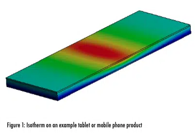
The notional temperature contour in Figure 1 illustrates a mobile device that cannot be accurately assumed as isothermal for the purpose of TDP calculations. In-plane thermal gradients develop along the length of the device, with a hot spot visible at its center.
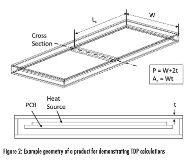
The underlying geometry for the example device is provided in Figure 2 and will be used to demonstrate the CTS and TDP calculations.
The device consists of a rectangular enclosure with a width W, a characteristic length Lc, and an enclosure thickness t. It is assumed a Printed Circuit Board (PCB) is within the enclosure, with the main heat source located at its center.
Many consumer electronics devices, such as tablets and mobile phones, exhibit a form factor similar to the example geometry. The large aspect ratio of these devices is reminiscent of a fin. In Figure 1, one could visualize two rectangular fins extending in opposing directions from the heat source at the center of the device. In this example, the hot spot on the enclosure corresponds to the temperature at the base of a fin, with two fins extending to either end of the product.
For large aspect ratio devices, it may also be acceptable to neglect the heat losses at the perimeter of the device because the surface area along the perimeter is often small in comparison to the surface area of the top and bottom of the device.
With these assumptions, the CTS of the device can be calculated using the fin efficiency equation for a rectangular fin with an adiabatic tip (equation (4)). This captures how effectively the surface area of the device can be leveraged when there are inplane thermal gradients.
Note that the characteristic length in this equation represents the distance from the heat source to the far extent of the device. In the simple example in this column, the heat source is in the center of the device and the characteristic length is half of the total length. Another possible embodiment would be to locate the heat source at the end of the device, in which the characteristic length would be the full length of the device. Thus, it is important that the characteristic length be adjusted as appropriate to the problem at hand.
The variable m in equation (4) is calculated using equation (5), where h is the combined heat transfer coefficient from the surface of the device, P is the perimeter of fin, Ac is the cross-sectional area of the fin, and keff is the effective in-plane thermal conductivity of the device.
The effective in-plane thermal conductivity may represent a single material such as a glass display or a composite stack such as a graphite layer adhered to a plastic substrate.
The perimeter in the example must be chosen to only include surfaces that reject heat to the environment. Since one surface of the fin is internal to the enclosure, it is neglected in the perimeter calculation (definition in Figure 2).
The fin efficiency calculated with equation (4) quantifies how well the front and back surface areas on the device are being utilized. The fin efficiency, or in-plane CTS in this example, is plotted against the non-dimensional parameter 1/mLc in Figure 3. As expected, the CTS is higher when either the effective in-plane thermal conductivity increases or the size of the device decreases.
Putting it into Practice
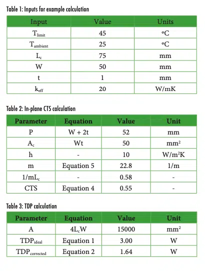
Now let’s demonstrate this for the calculation of a notional device with the inputs specified in Table 1. It is common for the environment, temperature limits, and desired form factor to be known.
The fin perimeter and cross-sectional areas are first calculated from the geometry definition in Figure 2. For the purposes of this example, an effective heat transfer coefficient of 10 W/m2 K is assumed and accounts for both natural convection and radiation. For general situations, one can use empirical correlations [2] to refine the heat transfer coefficient for their specific circumstances. These parameters are input directly into equation (5) to calculate m, which is then input into equation (4) to calculate the CTS (or fin efficiency). Per Table 2, the resulting CTS for this device is 0.55. In other words, the heat transfer from the non-isothermal surface is equal to an isothermal surface with 55% as much area.
The resulting TDP for the device, when corrected for in-plane thermal gradients, is 1.64 Watts (Table 3). This is lower than the ideal TDP of 3.00 Watts. If additional capability is required, the thermal designer can iterate this process to converge on a more satisfactory set of design parameters (e.g., size, material, etc.).
Concluding Remarks
This first-order method provides the thermal engineer with a tool to quickly estimate the thermal design power limit for devices that experience in-plane thermal gradients. This approach is well suited for architecture studies in which the design is rapidly evolving and estimates are needed to guide the design team. While this method can be very useful, it does not replace detailed design and validation. It is instead intended to refine the design concepts before transitioning to more detailed simulations and/or tests.
Since real products experience through-plane as well as in-plane thermal gradients, future work is planned to extend the approach to also account for the impact of through-plane thermal gradients.
References
[1] Victor Chiriac, “A Figure of Merit for Smart Phone Thermal Management”, Electronics Cooling Magazine, April 2017
[2] Frank Incropera and David DeWitt, Fundamentals of Heat and Mass Transfer, 4th Edition, Wiley (1996)


