Introduction
Effective cooling is essential for CPUs, as they generate significant heat during operation while being very temperature sensitive. Improved cooling allows for maintaining the functionality of high-performance computer hardware. In this article, we demonstrate a unique approach to improving the cooling of high-performance components by combining thermal and flow-based topology optimization methodology with additive manufacturing of highly conductive copper, with experimental validation of the results.
Generative Design: The Key To An Optimal Heatsink
Generative design uses Artificial Intelligence (AI) technology to generate one or multiple designs, starting only from system requirements, such as materials, boundary conditions, objectives, and constraints. Different techniques exist to gather and process information from subsequent design iterations. A popular strategy uses topology optimization. Contrary to traditional design methods, such as parametric and shape optimization, topological optimization does not require an initial design input, only the definition of a design space.
In this case study, generative design was applied to optimize the cooling channels in a CPU cooler. By minimizing a cost objective and meeting operational and manufacturing constraints, the process generated an ideal solid structure within a fluid, seeking the most efficient material distribution in accordance with the design objectives.
Copper: An Attractive Material For Heat Sink
Copper’s high thermal conductivity (398 W/m K)) makes it an interesting material for 3D printing of thermal management components. However, its high reflectivity for conventionally employed infrared lasers (wavelength of 1070 nm) limits the absorption of the laser light for melting. Furthermore, its high thermal conductivity quickly dissipates the energy absorbed by the laser, which creates challenges in producing copper components with laser-based 3D printing technologies.
Several strategies are employed in the industry to tackle these issues. In this study, the approach of using laser-absorptive copper powders was chosen. This method has three benefits: (i) material can be melted in conduction mode with higher build rates, while the smaller deep melt pool dimensions lead to excellent print resolution, (ii) standard L-PBF (Laser Powder Bed Fusion) equipment, with reliable and high beam-quality infrared lasers, can be used, and (iii) laser absorptive powders have excellent flowability and oxidation-resistant properties. These allow printed copper components to be produced in a broad and stable processing environment.
In addition to conductivity, material yield strength and specific weight are important when designing complex-shaped thermal management components with fine features [1,2].
The primary advantages of this approach are (i) the full density and a good combination of conductivity and strength: tensile strength up to 630 MPa, yield strength up to 510 MPa, ductility up to 30%, electrical conductivity up to 90% IACS, and thermal conductivity up to 360 W/(m K) for CuCr1Zr material; (ii) the ability to form thin-walled and complex-shaped structures with thickness down to 200 μm; (iii) the broad processing window allows repeatable and reproducible build quality; (iv) final part properties can be tailored to an application; and (v) the approach works with a 400 W laser that does not overheat the baseplate and powder, which improves powder recyclability.
Modeling the CPU Cooling System
A liquid CPU cooler typically consists of one or multiple solid parts and a liquid coolant. Simulation of this type of system is known as a Conjugate Heat Transfer (CHT) problem. The Navier-Stokes equations [3], consisting of expressions for the conservation of mass, momentum, and energy, are solved in the fluid domain. Closure of the momentum equation is provided by applying turbulence models to compute the turbulent viscosity. Various turbulence models exist; RANS, which is the most widely used for wall-bounded flows, was used for this case study.
For the solid region, only conservation of energy applies [4]:
where ρ, cp, κ and T are the material density, specific heat, thermal conductivity, and temperature, while Q refers to the heat source.
Heat transfer between the solid and the fluid depends only on the local physical properties and the temperature difference between the respective cells adjacent to the wall. At this wall interface, equilibrium conditions are imposed, which dictates continuous heat flux and temperature over the interface. While computationally expensive, this approach provides detailed insight into the physics of the problem, which gives the optimizer a more realistic characterization of each design. This is fundamental to accurately exploring the design space and eventually finding an optimal design.
Defining the Optimization Problem
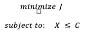
The objective/constraint formulation is a common method for defining and solving optimization problems. In this approach, an objective function expresses the goal of the optimization problem, which is subject to constraints that limit the solutions to those that satisfy certain conditions:
In the iterative design process, calculations are performed using adjoint equations to determine the sensitivity of the objective function to each system variable and to compute gradients for optimization. Examples of objectives are minimizing temperature or weight, while examples of constraints are a maximum allowable pressure drop or any manufacturing-related limitations.
CPU Cooler: Comparative Case Study
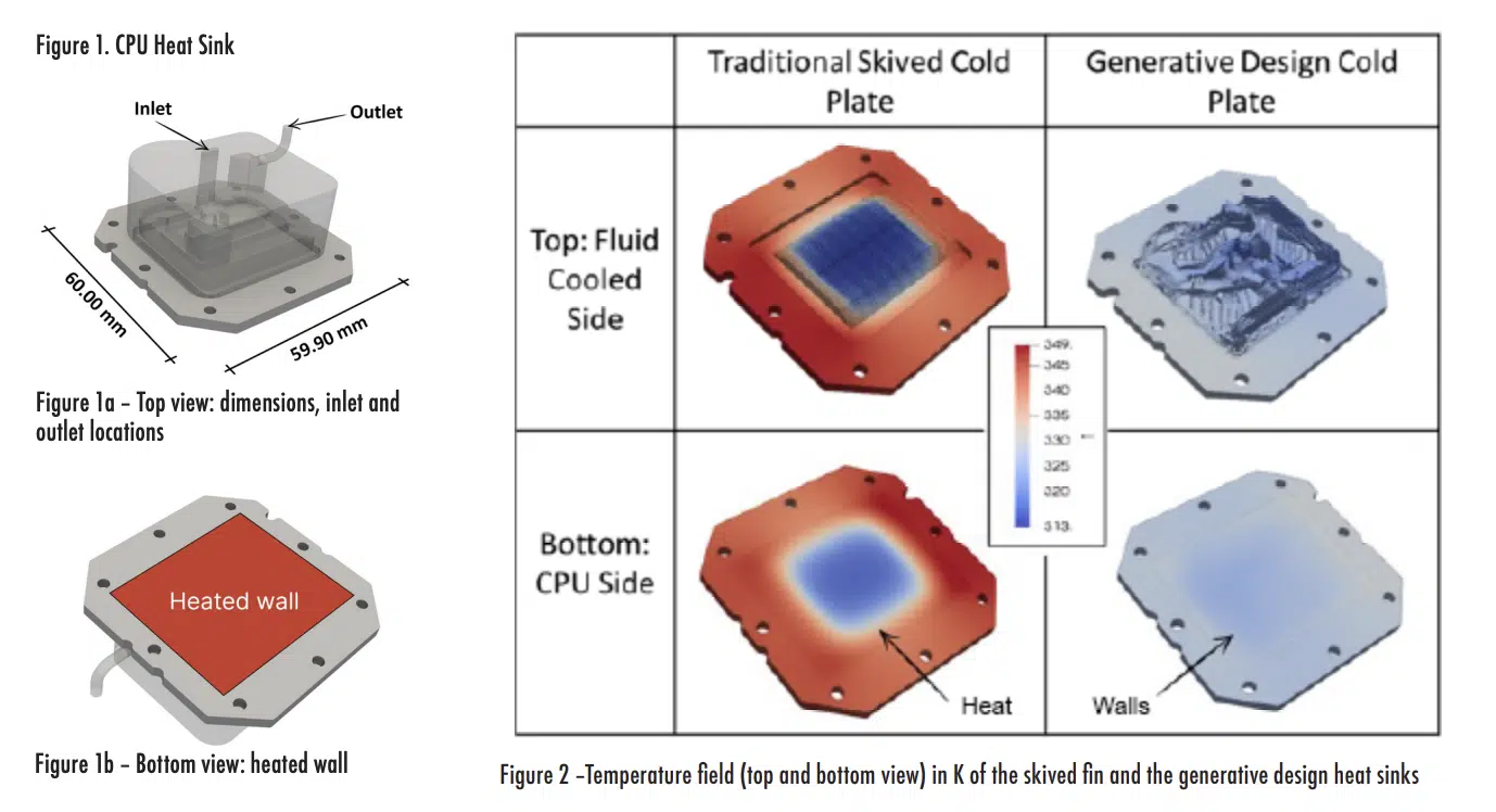
The case study compares a commercially available skived fin heat sink with one using a generative design using the same materials, operating conditions, boundary conditions, and outer envelope for both models. The base plate has dimensions 60.0 × 59.9 mm2 (Fig. 1a). The material of the heat sink is the copper used for L-PBF with ρ = 8910 kg/m3 , cp = 370 J/(K kg) and κ = 360 W/(m K).
The coolant is a 40/60 mixture of water and ethylene glycol with ρ = 1050 kg/m3 , the dynamic viscosity of μ = 0.00178 Pa s, cp= 3220 J/(K kg), and κ = 0.376 W/(m K). The inlet flow rate was fixed at 0.82 L/min and T = 313.15K (40ºC). Fig. 1a shows the inlet and outlet locations of the coolant.
The modeled heated wall (Fig. 1b) was an Intel 1700 that uniformly dissipated Q = 250 W over the contact area between the CPU and the heat sink.
Traditional design
The simulated temperatures of the skived fin copper heat sink are shown in Fig. 2 for the liquid-cooled side and the surface attached to the CPU. The traditional design shows a maximum temperature of 349.3K (76.1ºC), with the system cooling it down to 316.2K (43.0ºC). The temperature variance of the contact surface between the heat source and the heat sink is 124.6 K2 and the pressure drop was 11 kPa.
Generative design
The generative design utilizes targets and constraints to develop an optimized model. The target for the design was minimizing the temperature of the heated surface. This goal function reduced the temperature across an element by focusing on the highest temperatures:
where J is the value of the objective in K, T is the temperature distribution on a boundary in K, and S is the surface of the boundary where the objective is calculated in m2 .
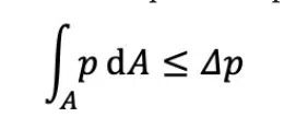
The inlet is constrained to a static pressure drop in the flow through the heat sink that is less than or equal to the prescribed value:
where p is the actual pressure at the inlet, and Δp is the allowable pressure drop, set as Δp = 11 kPa.
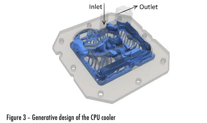
Fig. 3 shows the final generative design for the CPU cooler setup. The natural freeform shape combines large and small channels without symmetry.
The simulation results for the generative-designed heat sink are shown in Fig. 2 for the liquid-cooled and heated sides. The temperature on the heated wall ranges from 323.4K (50.3ºC) to 329.6K (56.4ºC), and its variance is 2.4 K2 .
The design region was modeled with 17M design variables. The full optimization loop and the CFD analyses were run in parallel on 256 CPUs.
Discussion
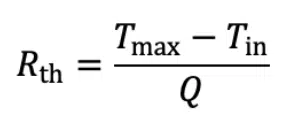
To compare the heat sink performance, the thermal improvement is calculated using the thermal resistances of each of the models:
where Tmax is the maximum temperature on the heat source and Tinlet is the inlet fluid temperature.
The thermal resistance of the skived heat sink was 0.145 K/W, while the resistance of the generative design model was 0.066 K/W – a 54.5% lower thermal resistance.
In addition, the temperature range is about 33K for the skived heat sink and only 6K for the optimized design. Although not explicitly imposed as a target, a uniform temperature is important to ensure uniform thermal degradation over the chip.
The difference in temperature variances on the heated source (CPU) is visible in Fig. 2. The more uniform temperature in the generative design model is due to the distribution of the cooling channels along the total area of the heated source (Fig. 3). The skived fin heat sink occupies a smaller area when compared to the heated source, which reduces the fluid flow pressure drop at the expense of less uniform CPU cooling.
Experimental Validation
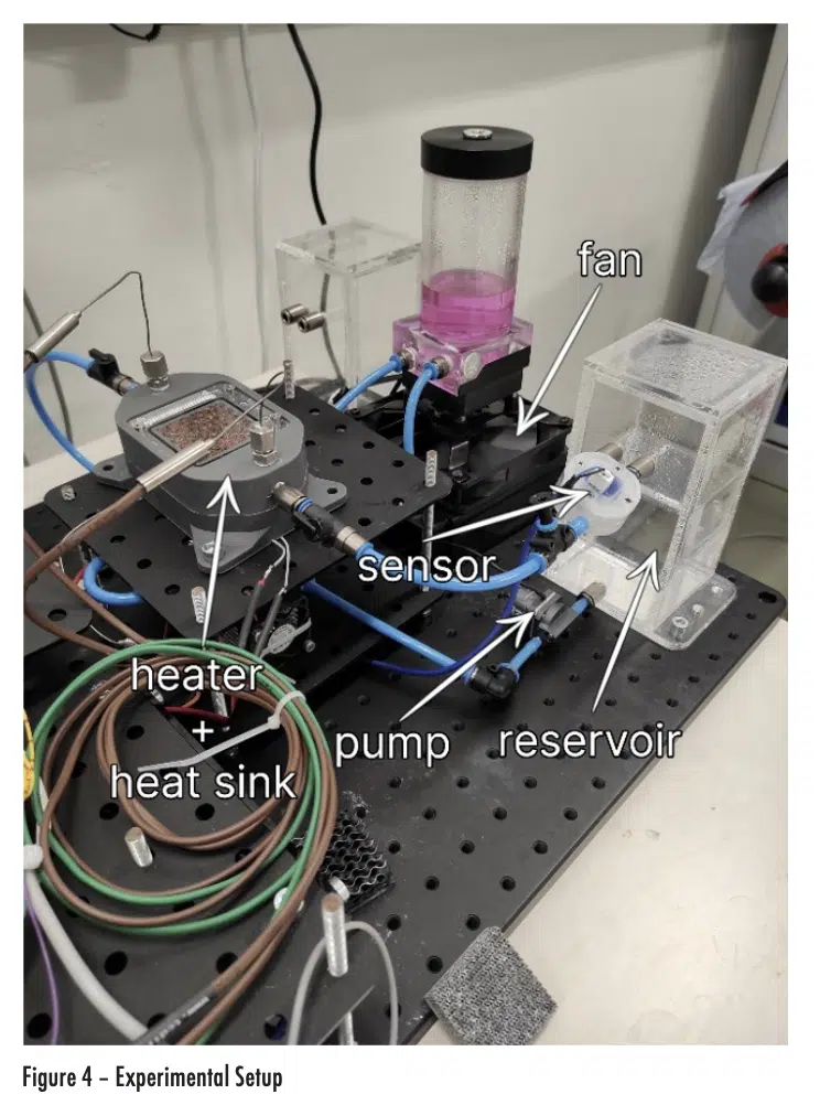
An experimental study was carried out to validate the results of the optimized CPU cooler. Due to laboratory testing constraints, test boundary conditions Diacould not match simulation conditions. Therefore, new numerical simulations with updated materials and operating conditions matched the experimental test conditions (Fig. 4) were made.
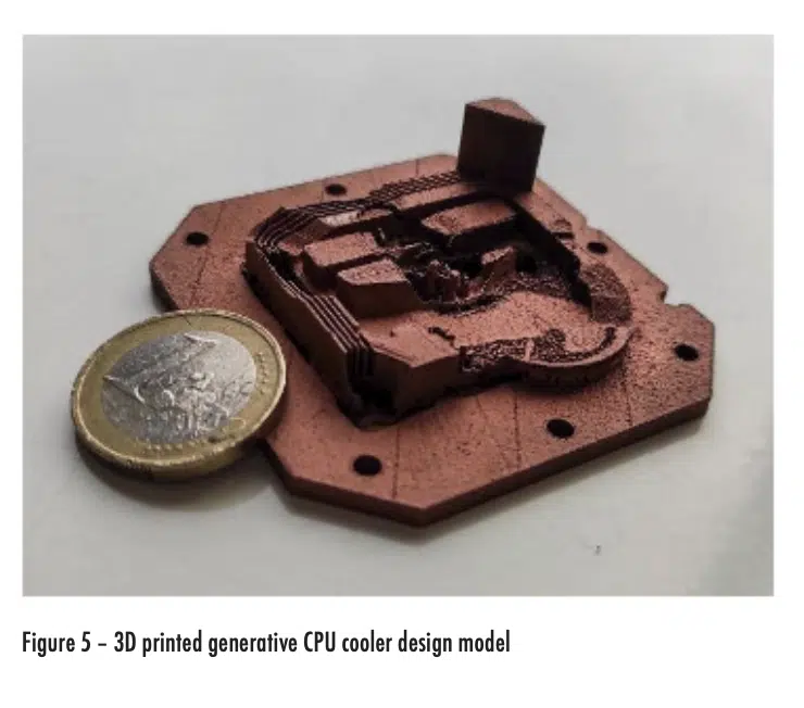
As mentioned, manufacturability was treated as a design constraint when defining the design region to ensure the design could be 3D printed; the resulting device is displayed in Fig. 5.
The top and bottom housings were fabricated in thermoset epoxy, with the following properties: ρ = 1150 kg/m3, cp = 1100 J/(kg K) and κ = 0.17 W/(m K). The heat sink material is L-PBF copper, with the properties already described. The main differences between the test and design configurations were the coolant and the heating system. Deionized water, with ρ = 998 kg/m3 , cp = 4182 J/(kg K), κ = 0.598 W/(m K) and μ = 0.001002 Pa s, was used as the liquid coolant. The system received 22.5 W of heat to represent the chip, modeled as silicon nitride (ρ = 3210 kg/m^3, c_p = 750 J/(kg K) and κ = 40 W/(m K)), and the heat was spread with a copper patch (ρ = 8960 kg/m3 , cp = 385 J/(kg K) and κ = 386 W/(m K)).
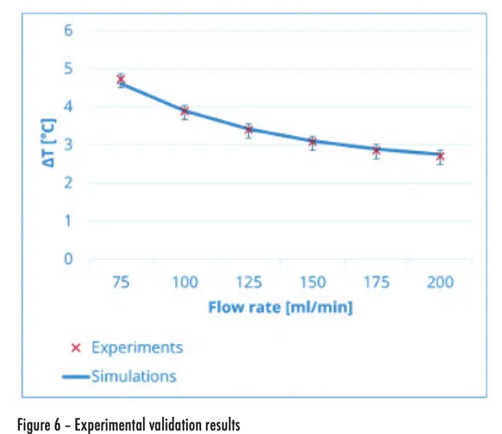
The heat sink’s performance (∆T=Tmax,heater-Tinlet,coolant), including uncertainty, is shown for flow rates ranging from 75 to 200 ml/min in Fig. 6. The experimental data corroborates the simulated values within the uncertainty interval, showing a very good agreement between them.
It must be stressed that 3D printing is not required for generative design. Other methods, such as milling and die casting, can be adopted by applying the manufacturing constraints.
Conclusion
The value of the generative thermal design process was illustrated through the design of a CPU cooler. The methodology autonomously suggests cooling system geometries in natural freeform shapes to reach an optimized design. The performance of a generatively designed heat sink was compared to a commercial copper skived fin design. The thermal resistance was improved by 55% in the generative design CPU cooler, which also greatly reduced heat source temperature variance. Experimental results matched simulations, showing that generative design offers a way to break new ground in thermal design.
Acknowledgments
Experts from Diabatix and Amnovis conducted this study. The generative design and the CFD simulations were performed using ColdStream by Diabatix [5] and 3D-printed by Amnovis [6]. KU Leuven performed the experimental tests.
References
[1] Jadhav, S.D. et al, 2019. Influence of carbon nanoparticle addition (and impurities) on selective laser melting of pure copper. Materials, 12(15), p.2469.
[2] Jadhav, S.D. et al, 2020. Mechanical and electrical properties of selective laser‐melted parts produced from surface‐oxidized copper powder. Material Design & Processing Communications, 2(2), p.e94.
[3] C. Hirsch, 2007. Numerical computation of internal and external flows: The fundamentals of computational fluid dynamics. Elsevier.
[4] K. Shea, R. Aish, and M. Gourtovaia, 2005. “Towards integrated performance-driven generative design tools”. In: Automation in Construction 14.2, pp. 253–264.
[5] https://coldstream.diabatix.com.
[6] https://www.amnovis.com/copper-lpbf.
