Introduction
Many programs geared toward the design of autonomous vehicles have been initiated in recent years. Waymo, Cruise, Baidu, Argo AI, Uber, Lyft, and Tesla are among the innovative self-driving car companies. Advances in autonomous technologies will require enhanced thermal protection of critical electronics to ensure optimized performance, health, and lifetime.
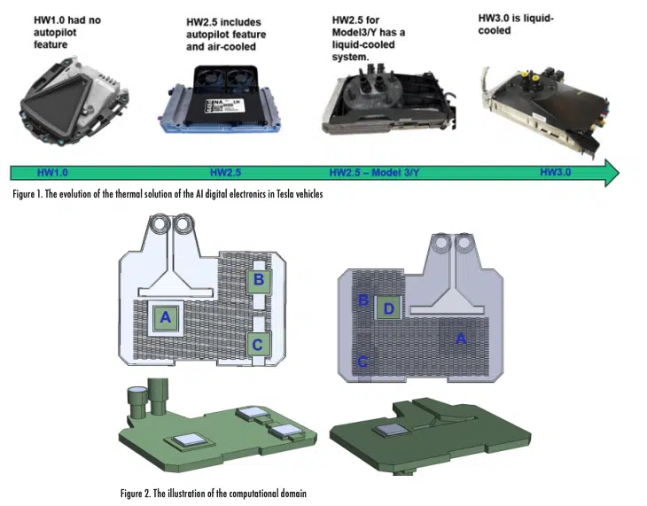
Emerging intelligent autonomous systems are increasingly complex while also required to have smaller size and weight. Packing more functionality into smaller footprints increases the heat density and thermal challenges. As shown in Figure 1, liquid cooling has been effectively leveraged to meet Artificial Intelligence (AI) digital electronics requirements in Tesla vehicles.
In this study, the hydraulic and thermal characteristics of the Tesla Autopilot HH2.5 Model 3Y module were investigated in detail. Two units were used in the study. The unit housing and the attached boards were removed to access the cold plates. One of the two cold plates was cut in half so that detailed internal dimensions, locations of the fins, inlet/exhaust ports, pedestals, and cold-plate channels could be measured. The information was used to generate a reliable CAD representation of the cold plate. A test vehicle was constructed using the second cold plate so that hydraulic pressure drops and thermal performance could be measured.
A computational fluid dynamics (CFD) model was constructed using commercial software [1] to evaluate the cold plate used in the test module. The CFD model was run with equivalent heat loads placed at the same locations as in the test vehicle and with fluid flowing at the same rate as in the experimental setup unit. The CFD results were then compared to the test data. A good correlation between the test data and the simulation results was found.
Part 1 of this set of articles describes the construction of the CFD model and the simulation results that examined the hydraulic and thermal performance of the cold plate across a range of operating conditions. Part 2 will include the step-by-step tear-down process of the unit, the experimental set-up, validation of the CFD model, and a description of the development and use of the Artificial Neural Network of the cold plate assembly to study the performance of the system at a wide range and combinations of the operating parameters.
Numerical Simulations
CFD simulations were carried out using the commercial code and assuming that the flow and temperature fields were steady state. The continuity and momentum equations along with the energy equation were solved numerically for the pressure, velocity, and temperature fields using the finite volume method. To divide the computational domain into discrete control volumes, more than 1.5 million non-uniform 3D tetrahedral computational cells were used.
As shown in Figure 2, four 25.4 x 25.4 mm die were mounted to the cold plate. These die locations are labeled to provide reference points for the discussion in this article.
To study the thermal performance of the cold-plate, a constant heat load of 125.5 W was applied to each of the 25.4 mm x 25.4 mm x 2 mm rectangular prisms representing the chips located on the cold plate pedestal. A Network Resistance model was assigned to each heater representing the chips. The junction-to-case and the junction-to-board resistances were set at 0.1 and 1,000 ºC/W, respectively to ensure that the heat dissipated by each chip was rejected to the cold plate. A thermal interface material with a thickness of 0.25 mm and a thermal conductivity of 10 W/m-K was placed between the cold plate and the heaters. The liquid was assumed to be 50/50 Glycol/water with constant heat capacity, density, thermal conductivity, and viscosity of 3,800 J/kg-K, 1040 kg/m3 , 0.36 W/m-K, and 0.006 N-s/m2 , respectively.
Results and Discussion
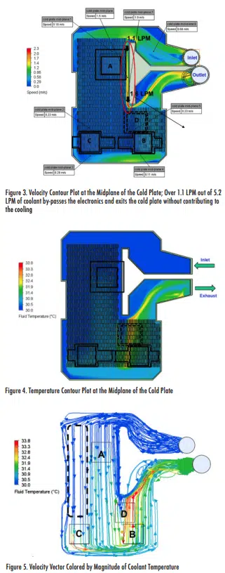
Contour plots of the temperature and velocity fields are illustrated in Figures 3 and 4 to provide insight into the performance of the cold plate and to identify opportunities for design improvements. Coolant inflow temperature and the flow rate were set to 30ºC and 5.2 liters per minute (LPM), respectively. The cold plate thermal conductivity was 113 W/m-K and the thermal load per chip was set to 125.5 W. The region with no fins had the lowest hydraulic impedance. Therefore, as shown in Figure 3, a large percentage of the coolant bypassed the chips and exited the cold plate without making a significant contribution to the heat removal. The flow through the bypass increased with length, indicating that the flow was leaking from the fin stack along the length to the bypass region. The average velocities in the vicinity of Chips B (0.4m/sec) and D (0.3m/sec) were higher than in the vicinity of Chips A (0.2 m/sec) and C (0.2m/sec).
The average bulk temperature of the coolant at the exhaust side of the cold plate was 31.4ºC. The average temperature of the coolant beneath Chips B and D was higher than the average liquid bulk temperature. This is illustrated by the fluid particle trajectories shown in Figure 5.
Cold fluid by-passed Chip A and approached Chip C. Therefore, the average temperature of the fluid as it approached Chip C was independent of the power dissipation of Chip A and could be approximated by the coolant inlet temperature. Chips B and D are located downstream of fluid that passed beneath Chips A and C. The heat dissipated by Chips A and C was exhausted from the cold plate into the fluid before the fluid approached the region in the cold plate below Chips B and D. High power dissipation by Chips A and C and/or a lower fluid flow rate results in a higher fluid temperature as the fluid approaches Chips B and D. This in turn results in higher temperature for Chips B and D as compared with the temperature of Chips A and C.
Some of the liquid trajectories beneath Chips B and D take a V-shape path as they pass through the cold plate. The result is a longer contact time with the die and therefore a higher temperature for those particle trajectories.
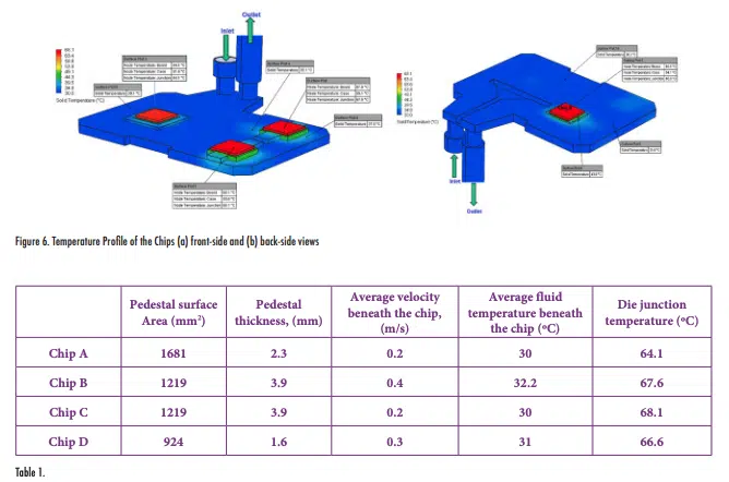
The temperature contour plots of the chips and the cold plate are shown in Figure 6. The maximum temperature difference between the four chips was 4ºC. The cold plate can remove 4 x 125.5 W = 502 W from these chips while maintaining chip junction temperatures well below the temperature limit of 90ºC.
For a given flow rate, assuming identical power load, dimensions, and TIM for all four chips, the temperatures of the chips depend on four interrelated factors: the thickness and surface area of the pedestal, cold plate flow distribution, and fluid temperature in the vicinity of the chip. The effect of the pedestal presumably is a combination of thickness and area since it acts as both a vertical conductor and horizontal spreader. Theoretically it is expected that the temperature of the chip increases with an increase in the thickness of the pedestal or the coolant temperature beneath the chip. Furthermore, the temperature of the chip is expected to increase with a decrease in the surface area of the pedestal or the velocity of the coolant beneath the chip. Table 1 summarizes the impact of the four interrelated factors on the chip temperatures.
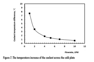
From conservation of energy, the greater the coolant flow rate, the smaller the gradient of the coolant temperature across the cold plate. The temperature increase of the coolant across the cold plate as a function of the coolant flow rate is shown in Figure 7.
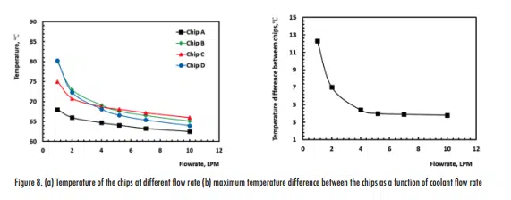
As shown in Figure 8, chip temperatures increase with a decrease in the coolant flow rate. The study shows that chip temperatures were dependent on the flow rate. Chip temperatures began to increase dramatically once the flow rate went below 4 LPM. The temperature variations between the chips also increased as the coolant flow rate decreased. The difference in chip temperature was 4ºC and 12ºC at 10 LPM and 1 LPM, respectively. Chips from the lowest to the highest temperatures were A, D, B, and C, for flow rates above 4 LPM.
Conclusion and Summary
In this study, the hydraulic and thermal characteristics of an autopilot module were investigated in detail. The unit includes a double-sided cold plate with circuit boards attached to each side of a cold plate. One unit was torn down to measure the detailed internal dimensions, locations of the fins, inlet/exhaust ports, pedestals, and cold-plate channels. That information was used to generate a 3-D numerical model of the module using commercial CFD software. Results from simulations that examined the hydraulic and thermal performance of the cold plate are presented in this article. The follow-on article, Part 2, will include a step-by-step description of the tear-down process of the unit and the experiments that measured the hydraulic head loss through the cold plate and evaluated the thermal performance at several coolant flow rates and power loads. The test results were used to validate the CFD model. It will be shown that the model results for the hydraulic pressure loss and temperature profiles were consistent with the experimental data. An Artificial Neural Network (ANN) of the cold plate assembly was then developed using the CFD results presented in this paper. The ANN model was used to study the performance of the system at a wide range and combinations of the operating parameters. In Part 2, it will be demonstrated that the developed ANN model could be used to determine the performance limit of the cold plate.
References
[1] Simcenter Flotherm XT 2021.1, Siemens Inc., https://plm.sw.siemens.com/en-US/simcenter/fluids-thermal-simulation/flotherm-xt/
