Continuing from part 1, and the advantages of thermocouples, we will now visit the process to make a thermocouple and its measurement system.
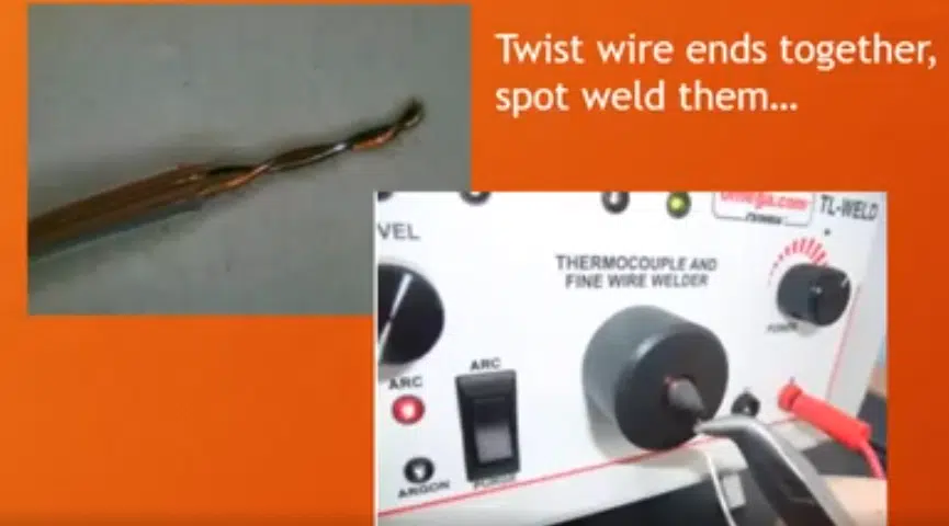
The way thermocouples are made is very simple. We have a thermocouple welder, shown in Figure 1, as a small machine. The ends of the two wires are twisted to digital wires together, and then each set of wires touches to the point where a relatively high voltage is generated. That generates a small arc, and that weld spot holds the two ends of the wires together. Through this process, we can make as many as we need with the reels of wire at a low cost. This way also proves to be customizable, and although one meter is standard, we can make it as long or as short as needed.
The next step is to test the thermocouples. The test protocol is where we can check the accuracy of the thermocouples before they are used. In the figure below, there are examples of eight different thermocouples, and they all show the same temperature with some variations. The variations are due to room temperature variables.
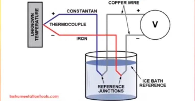
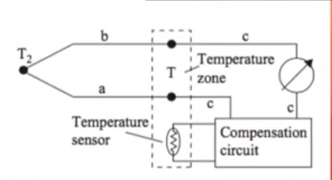
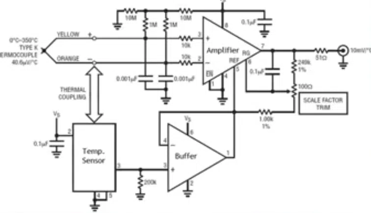
The original way of using thermocouples was to have a reference junction in the ice bath, shown in Figure 2, because it is not on the absolute temperature that the voltage is generated. The voltage difference is between the hot junction and the reference junction. In a psychics lab, or something similar, an ice bath gives a guaranteed reference temperature. This is impractical for most applications because you cannot use that in a normal lab. An alternative to having a reference junction is quite simple to do using a particular type of a compensation circuit (Figure 3). The compensation circuit injects a small amount of current into the signal, which then compensates for the temperature. This will then measure the temperature at the cold junction to room temperature. A simulated cold junction is created when Then it calculates a general compensation current it can inject the equivalent of room temperature and ice bath at zero degrees. This is constantly measured with its own small temperature sensor so that this remains accurate. The temperature zone is the most important, which means that the temperature sensor and the cold junction temperature are physically close together. The compensation circuit could inject the wrong compensation current, so it is imperative that they are all together to emit the same temperature. If done correctly, it is an accurate way of generating a stable cold junction temperature reference.
There are ICs that have this all built in, so there is no need to reinvent the wheel and it is possible to buy these as a complete unit. These are referred to as thermocouple amplifier ICs. There is a very high gain amplifier, which will take a small voltage that is being generated by the thermocouple and boost up to a more stable measurement in this case. This circuit will then go from a few microvolts per degree Celsius to then a generated signal that produces ten millivolts per degree Celsius. It has a built in temperature sensor and a compensation generator so that the reference for the amplifier is compensated for an accurate signal.
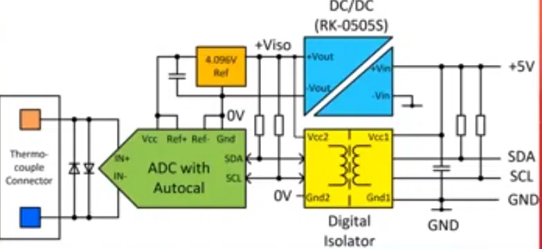
Unfortunately, anything with such a high gain will also amplify any input voltage and offset. Offset is the difference that the amplifier sees on its positive and negative inputs. Any offset drift will be amplified, so it will need to be compensated for that as well. The alternative is to keep swapping over the inputs. This way there is little circuit which switches over the plus and minus on the amplifier backwards and forwards. As you can see from Figure 4 below, an ADC was used to have all this together. This serves as the input amplifier. It has an internal temperature sensor, and internally will convert that analog signal to a digital output using a squared C serial interface. There is not only cold junction temperature compensation there, but also auto calibration circuit. This means that it will calibrate itself and sort itself out within a small three millimeter by three millimeter SMD package. In the figure below, the small package is underneath the connector. The thermocouple connector comes into the socket, and then it is on the other side of the board just underneath. There is a programmable gain, the cold junction compensation, auto offset calibration, and digital output. The digital output is needed nowadays for a modern lab.
After trial and error, we came to the conclusion that since thermocouples are made of metal, if they are connected to a device with high voltage, like an ACDC converter, can cause major damage to the whole circuit. Although all the supplies can be bought off the shelf, for testing it is not guaranteed that connecting the thermocouple to a voltage free point and you do not want to earth your circuit through the thermocouples. From here, there was a redesign and have a digital isolator from the digital output. Once there is a digital isolator on the output, then you have to provide isolated power. A DCDC converter has an isolated supply. From the Figure 5 &6 below, the simple block diagram is what is needed to make an accurate thermocouple measurement system with I2C connection.
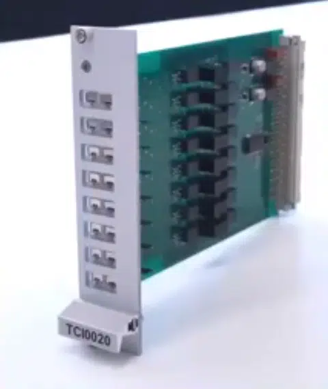
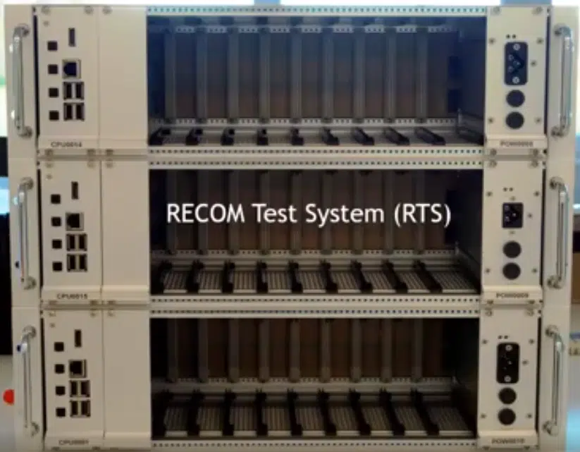
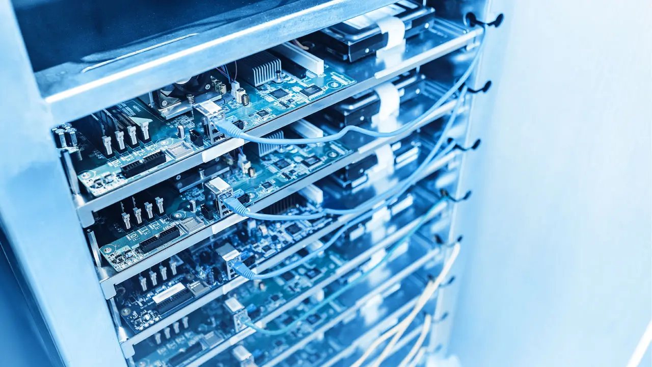
An isolated temperature sensor module is built from these units. A 90 rack system is used for testing, and as shown from Figure 7, the cards shows eight channels on one card. Then we multiply the I2C data lines, and it is bidirectional. This means that the information can be sent to ADCs as well, so then they are instructed to do the auto-calibration to set that up, set the gain up and everything depending on what type of thermocouple is being used, and the data being read back. Every single one of the eight inputs is completely isolated electrically, so there is no danger of short circuit when actually tested.
