As most readers are aware, the data center industry has put an increased focus on energy efficiency and environmental impact. Data centers in the United States are estimated to consume nearly 2% of the total electricity. The de facto metric used in the data center industry to evaluate energy efficiency has been the Power Usage Effectiveness (PUE), as defined by The Green Grid [1]. As defined by Equation 1, PUE is the ratio of the total power that enters the data center facility (including cooling, power distribution losses, lights, HVAC, IT Equipment, etc.) to the power provided to the IT equipment.
 |
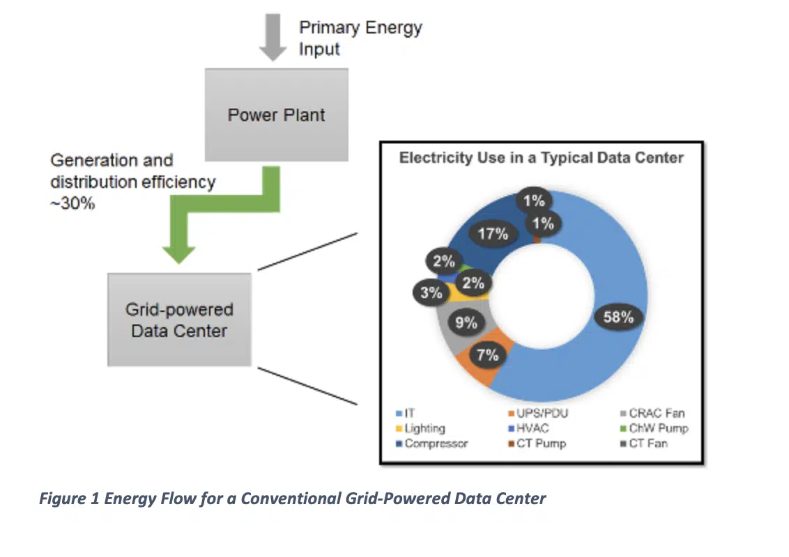
Recent surveys [2, 3] have shown that the average data center PUE is still greater than 1.7. This means that for every 1.0 watt of IT Equipment power, another 0.7 watts are needed to deliver power and cooling. An example breakdown of the power use in a data center is shown in Figure 1. This example data center has a PUE of 1.71.
The PUE only accounts for the power distributed throughout the data center. In almost all cases, this electricity is generated and delivered to the data center from a remote power plant. The actual primary energy required () to operate the data center is given by,
 |
The efficiency in the denominator of Equation 2 is the combination of the power plant’s thermal efficiency (hth) and the efficiency of transmitting and distributing the power (hdist) from the site of generation to the data center. The US Department of Energy and Energy Information Administration have reported that these distribution losses are typically about 7% [4].
Using On-Site Power Generation for Data Centers
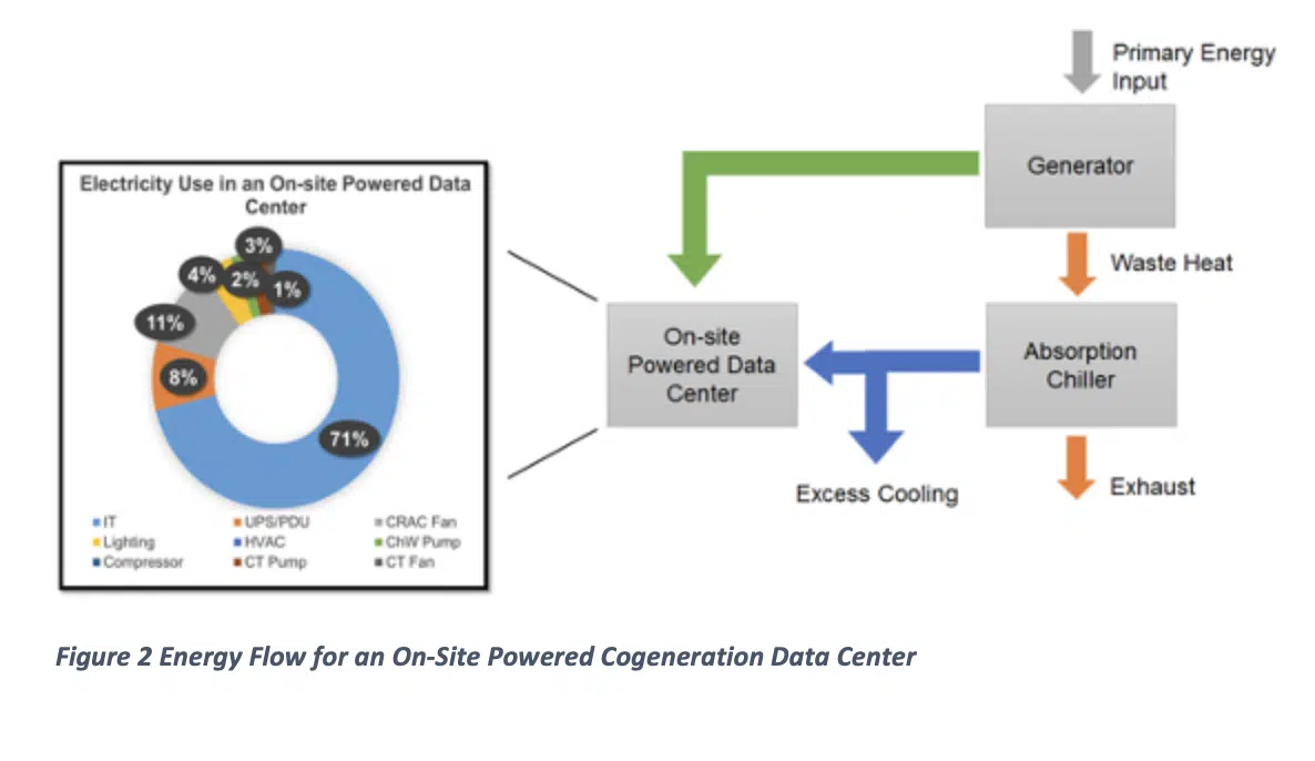
An on-site power generation system for a data center, as shown in Figure 2, provides a number of advantages compared to a grid-powered data center. For example, an on-site power generation system allows the use of the generator’s waste energy to provide cooling using a thermally-activated absorption chiller [5], otherwise known as a cogeneration system. Unlike many commercial buildings, a data center can provide a high utilization of the cogeneration system’s thermal output because its electrical and thermal demands are strongly correlated. Every watt of electrical power provided to the data center must be thermally removed. The use of an absorption chiller to provide cooling removes a substantial electricity demand due to the elimination of mechanical cooling.
To determine a PUE for a cogeneration system based data center, we can remove both the HVAC and compressor loads – as these are provided by the absorption chiller using the data center’s waste heat, with little to no electricity required. Additionally, the cooling tower pump and fan power requirements must scale accordingly since the absorption chiller coefficient of performance (COP) is much lower than a conventional vapor compression chiller. The condenser load on the chiller () can be computed as,
 |
where, is the evaporator load, which includes the IT power, uninterruptable power supply (UPS) and power distribution unit (PDU) losses, lighting, HVAC and chilled water pumps. The corresponding cooling tower pump power in the cogeneration system can be estimated by scaling the cooling tower pump power in the conventional data center, as observed in Equation 4.
 |
Similarly, the cooling tower fan can be scaled based on the condenser load. The corresponding PUE for a cogeneration system based data center, as shown in Figure 2, is 1.41. There are many other benefits to generating power on-site that can further reduce the PUE, including water cooling and DC power distribution. These are discussed in more detail in [6].
Primary Energy Requirement of a Cogeneration System Data Center
While PUE can be computed for a cogeneration system based data center, it does not highlight the complete picture when the generator waste heat is used to provide cooling for the data center. Instead, we will focus on the primary energy required for a data center that utilizes a cogeneration system, as described in [6], compared to a traditional grid-powered data center. Referring to Figure 2, the generator, which could be a turbine, gas generator, or fuel cell, has a thermal efficiency ( defined as,
 |
where the product of the IT power and the PUE is the work output of the generator. The absorption chiller has a thermal coefficient of performance (COPth) defined as,
 |
where is the cooling load, is the exhaust energy from the generator, and is a waste heat recovery factor. The recovery factor is a function of the effectiveness and dew point temperature limits of the absorption chiller and describes the fraction of useable waste heat. The first law of thermodynamics of the generator states that,
 |
By combining Equations 5, 6 and 7, the cooling output of the absorption chiller can be computed as,
 |
As shown in Figure 2, part of this cooling is used to cool the data center. However, depending on the generator thermal efficiency, excess cooling may be available to use for other cooling loads, such as a nearby campus building. The amount of excess cooling available is,
 |
In a conventional data center, this excess cooling would need to be provided by an electric vapor compression chiller. The primary energy that would be required to generate this excess cooling in a grid-power arrangement is given by,
 |
where COPe is the coefficient of performance of the electric vapor compression chiller. Therefore, the net primary energy for the cogeneration system data center is given by subtracting the offset (Equation 10) from the primary energy required by the cogeneration system (Equation 5).
Example of an On-Site Powered Data Center Compared to a Conventional Grid Powered Data Center
To highlight the energy savings of an on-site power generation system, we can use Equations 5 through 10 and the data center PUE as shown in Figures 1 and 2 for the conventional and cogeneration data center, respectively, to compare the primary energy required. We can show this as a percentage savings of the cogeneration system. Table 1 gives the parameters used in the analysis.
Table 1: Parameters used in example analysis of an on-site power data center. Values represent typical values for commercially equipment.
| Thermal efficiency, hth | 33% |
| Distribution efficiency, hdist | 93% |
| Electric Coefficient of Performance, COPe | 4.88 |
| Thermal Coefficient of Performance, COPth | 1.20 |
| Waste heat reuse factor, j | 58% |
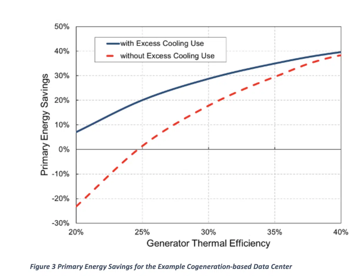
Figure 3 plots the primary energy savings of the cogeneration system data center versus the generator thermal efficiency. The solid line shows the savings when the cogeneration system’s excess cooling can be fully utilized, both to cool the data center and an additional cooling load. The dashed line shows the case where the absorption chiller cooling can only be used to cool the data center. This would be the case if the data center was isolated. It can be seen that compared to a grid-powered data center, with an overall 30% efficiency (generation + distribution), without being able to use the excess cooling, the on-site power system offers little to no advantage until the generator efficiency reaches greater than 25%. Many commercial microturbines can now offer thermal efficiencies nearing 28% [7]. When the excess cooling can be used, these systems can provide substantial primary energy savings, in excess of 20%.
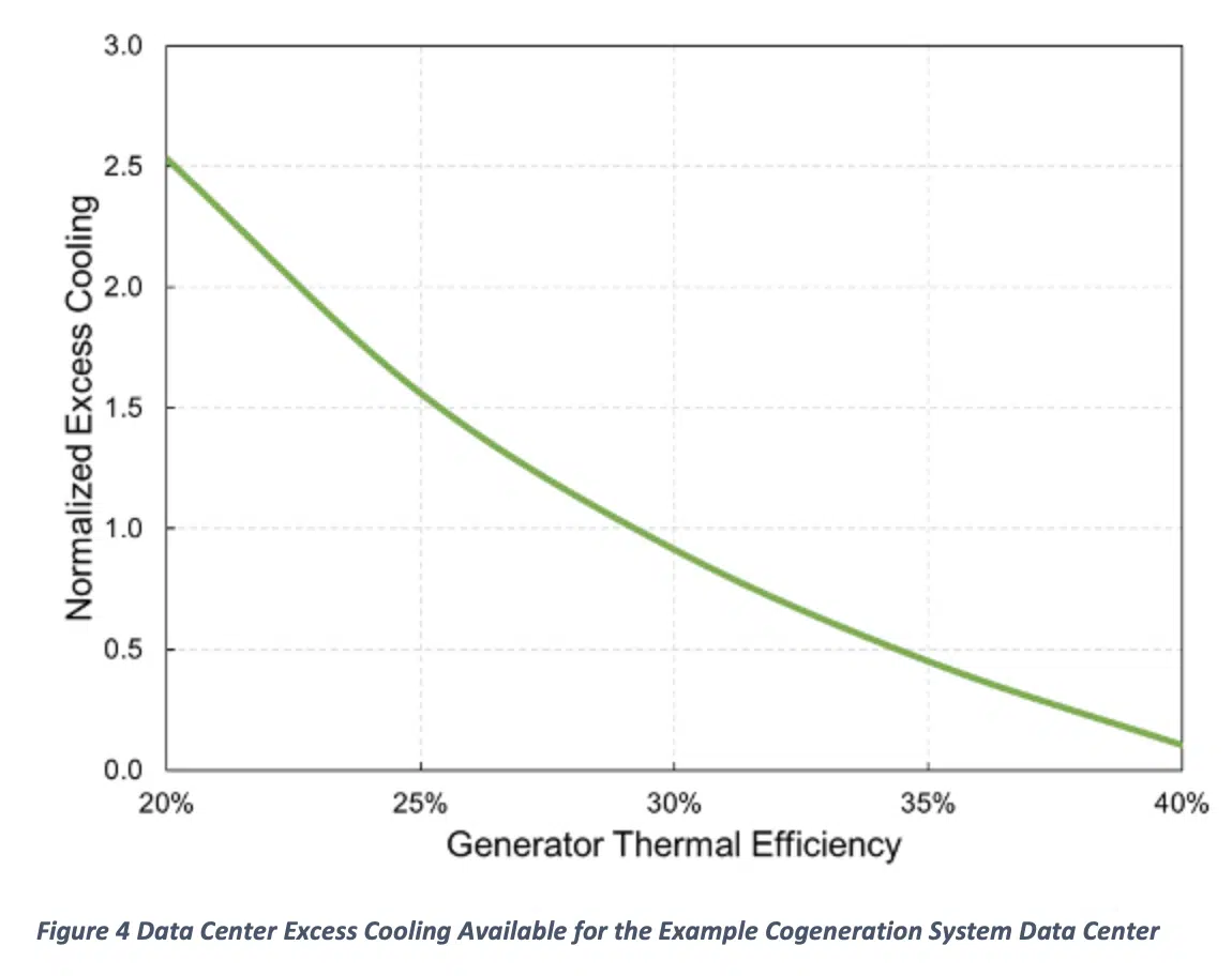
As the generator thermal efficiency increases, the amount of primary energy necessary to provide the required data center power decreases, as shown by Equation 5. By the first law of thermodynamics, this also means that less exhaust energy will be available to generate cooling in the absorption chiller. Figure 4 plots the excess cooling, which has been normalized by the data center power, versus the generator thermal efficiency. As the generator efficiency reaches 40%, which may be representative of a large gas generator or a stationary fuel cell, the excess cooling approaches zero. This means that the waste heat from the generator can be used to provide just enough cooling for the data center. Referring back to Figure 4, the higher the generator thermal efficiency, the more primary energy savings of an on-site power generation system. Additionally, when the generator efficiency nears 40%, the data center needs to rely less on having an additional nearby source to utilize the excess cooling, as seen by the solid and dashed lines converging.
Conclusions
This article showed how a simple thermodynamic analysis can be effectively utilized to analyze alternative power and cooling options for data centers. It highlighted the benefits of on-site cogeneration for data center applications, where the thermal and electric demands are strongly correlated. The article also described a primary energy methodology that shows the benefits of an on-site system compared to a traditional grid-powered data center.
Nomenclature
| COP | Coefficient of Performance |
| P | Power, kW |
| PUE | Power Usage Effectiveness |
| Energy, kW | |
| Greek Symbols | |
| h | Efficiency |
| Waste heat reuse factor | |
| Superscripts | |
| CG | Cogeneration |
| GEN | Generator |
| Subscripts | |
| c | Cooling |
| CND | Condenser |
| CT | Cooling tower |
| dist | Distribution |
| e | Electric |
| EVAP | Evaporator |
| ex | Exhaust |
| IT | Information technology |
| PE | Primary energy |
| th | Thermal |
References
[1] ASHRAE, 2014. PUE: A Comprehensive Examination of the Metric, ASHRAE Datacom Series 11
[2] Stansberry, M, “2014 Data Center Industry Survey,” https://journal.uptimeinstitute.com/2014-data-center-industry-survey/, last retrieved on August 24, 2015.
[3] Salim, M. and Tozer, R., 2010, “Data Centers’ Energy Auditing and Benchmarking- Progress Update,” ASHRAE Transactions, Vol. 116(1), pp. 109 – 117.
[4] Energy Information Administration (EIA), 2010, Electric Power Monthly, September 2010. Energy Information Administration, US Department of Energy, Washington DC.
[5] Herold, K.E., Radermacher, R., and Klein, S.A., Absorption Chillers and Heat Pumps, CRC Press, 1996.
[6] Erden, H.S. and Khalifa, H.E., 2012, “Energy and environmental assessment of On-site power and cooling for data centers,” HVAC&R Research, Vol. 18(1-2), pp. 51-66.
[7] U.S. Environmental Protection Agency, 2015, “Section 5. Technology Characterization – Microturbines,” Catalog of CHP Technologies, http://www.epa.gov/chp/technologies.html, last retrieved on August 24, 2015.


