Introduction
In recent years, integrated circuit chips have enabled increasingly powerful computing capabilities as advanced process nodes have moved from DUV (deep ultra-violet) to EUV (extreme ultra-violet) lithography, allowing for higher fabrication resolution and transistor density. Additionally, advanced multi-die packaging has seen increased market demand. As a result, the total thermal power as well as the thermal power density of systems are increasing, leading to the use of a heat spreader such as a metal plate or graphite sheet with good lateral thermal conductivity to relieve the thermal power density. Comparatively, the two-phase vapor chamber (VC) is an even more effective heat spreader in the lateral direction. The structure of a vapor chamber consists of a bottom plate (evaporator) and a top plate (condenser), both made of copper. In between, there are wick structures made of copper mesh and copper powders that contain a small amount of water. After the edges around the plates are sealed, the inner chamber is filled with water (the working fluid), and a vacuum is created inside the device. Other common combinations of VC material and working fluid include titanium/water and aluminum/ acetone. When the bottom plate is heated, the liquid in its wick structure evaporates and the phase change absorbs a large amount of latent heat. The heat is then carried away by convection of the vapor. When the vapor reaches the cooler top plate, it condenses back to liquid form, releasing the latent heat. The liquid then returns to the bottom plate by the capillary effect of the wick structure. Vapor chambers are an effective heat spreader because of their ability to absorb large amounts of latent heat during phase change, as well as their effective and uniform spreading of heat via the convection of vapor. Thin vapor chambers, with thicknesses less than 1 mm, are typically utilized in passive cooling designs where available space is very limited. This article discusses measurement challenges regarding thin vapor chambers.
Performance Measurement of Thin Vapor Chambers
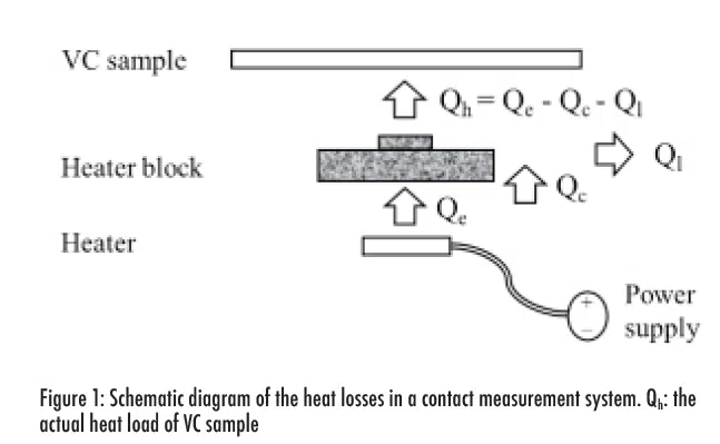
Traditionally, contact measurement has been used to measure VC performance. This method often involves the use of resistive rods/wires and ceramic heaters, with a copper block typically inserted between the heater and the vapor chamber to facilitate heat conduction. The thermal dissipation from the heater, Qe, can be determined from the electrical power, calculated as the product of current and voltage. The presence of the copper block introduces a temperature differential due to its own thermal resistance along the conduction path between the heater and the evaporator plane of the VC. The thermal capacitance of the copper block also stores energy during transient events. Although the copper block is typically insulated, heat losses due to lateral heat dissipation Ql from the copper block can be significant [1]. Figure 1 schematically shows the critical test components, VC sample, and the lateral heat loss path in a test setup that relies on contact measurements.
The heater design of commercial test equipment must also consider mechanical attachment for production line applications, which can make the design process even more complex. The temperature gradients due to thermal resistance and lateral spreading, as well as transient effects related to the thermal capacitance of test components, fundamentally limit the amount of heat that can be delivered to the DUT (device under test). The VC’s performance is dependent on the heat load since the amount of water in the VC is limited and the temperature uniformity of the VC cannot be sustained beyond a certain power level. An over-estimated thermal load may result in inaccurate OQC (outgoing quality control) and pose potential risks to the final system, making an accurate power estimate particularly important for VC testing. Thin vapor chambers with thicknesses less than 1 mm are typically used in cases when the power is less than 10 W and relative heat losses can be relatively large. Due to the thermal mass of the heater and copper block, contact measurement can also take several minutes to bring the thin vapor chamber up to its correct operating temperature for accurately testing the device. In summary, contact measurement methods are challenging for VC testing due to the required power delivery accuracy and increased cycle time.
A laser heater is an alternative method to precisely deliver thermal dissipation to the vapor chamber by radiation in the form of electromagnetic waves rather than conduction. The thermal conductor (copper block) is no longer necessary and therefore thermal resistance and thermal capacitance issues are eliminated. The directional power flow of electromagnetic waves is described by the Poynting vector S = E x H, i.e., the cross product of the electric field vector E to the magnetic field vector H. The output beam from a laser is highly coherent and directional, so the lateral power dissipation is negligible. The power of a collimated laser beam can be directly measured by a high-precision optical power meter. The issue of the accuracy of heat power is solved using the laser heater method [2, 3].
Temperatures at specific locations on the vapor chamber are measured for the test: including TJ at the heated location on the evaporator, TC on the condenser opposite TJ, and TX (5.0 cm away from TC) on the condenser side. The temperature measurement is also non-contact and uses infrared bolometers that detect thermal radiation from objects without contacting the sample. The TJ temperature is important because its position would be in direct contact with the chip. However, when using the infrared bolometer to measure the temperature at TJ, the laser would interfere with the detected signal. Therefore, the Time Domain Extinction Method was used to exclude the laser light from the measurement of TJ. In this method, the temperature is taken when the laser is switched off for a very short interval of time to avoid interference [3]. Using the non-contact method, measurements can be rapidly completed (within 60 seconds) because the temperatures obtained through this process are much closer to thermal equilibrium and much faster than when taken via contact measurement.
Constant Power Measurement
Figure 2 shows the measured results of (a) a vapor chamber and (b) a copper plate using the non-contact method under a power of 5 W. There are some notable differences between the non-contact and contact results. First, both the VC and copper plate temperatures increase rapidly with large slopes in the first few seconds after the onset of laser heating, while the temperature curves observed during the contact method have moderate slopes. Additionally, after heating for just 60 seconds, the VC temperatures TJ and TC reached around 55 to 60°C, which is significantly higher than those reached by the contact measurement over a much longer duration. These results confirm the power delivered to the VC via laser heater is significantly higher than that of a contact heater over the 60-second test duration.
The temperature uniformity, TC-TX, is a measure of heat spreading ability. A smaller value indicates the heat effectively spreads over a larger area. Since the heat is less concentrated around the heating spot, TJ decreases. Comparing the VC and the copper plate, TC-TX is well within 5°C for the VC, as shown in Fig. 2(a), while it is more than 15°C for the copper plate in Fig. 2(b). Therefore, the two-phase operating mechanism of a VC is more effective than the thermal conductivity mechanism of a copper plate. TJ of the vapor chamber is 53.9°C and is about 8°C cooler than that of the copper plate.
Regarding power dissipation, since the amount of water in VCs is limited, great care should be taken when using them. When the power goes beyond Qmax, the two-phase cycle of liquid water and vapor can no longer be sustained. This is because excess thermal dissipation causes the water in the wick structure around the heater to dry out. For a power of 9 W (higher than Qmax), TC-TX is greater than 15°C while TJ goes up to as high as 73.1°C, as shown in Fig 3.
Transient-state Measurement
The thermal capacitance in the contact heating method is a limiting factor in transient measurements. The transient response of the vapor chamber was experimentally measured for tens to hundreds of seconds after the onset of heating [4]. The transmission of mobile communication data occurs in bursts, where the transmitted power is boosted for a short period of time, to improve signal to noise ratio and spectrum reuse efficiency, and the thermal dissipation is proportional to transmitted power. Understanding the transient response of the vapor chamber can provide more information to system designers. The semiconductor laser can serve as a function generator of power dissipation by controlling the drive current to generate a variety of profiles, such as a single rectangular pulse. The transient response of the VC can be accurately measured using the laser heating method with a fast response since the thermal capacitance of the copper block is no longer there.
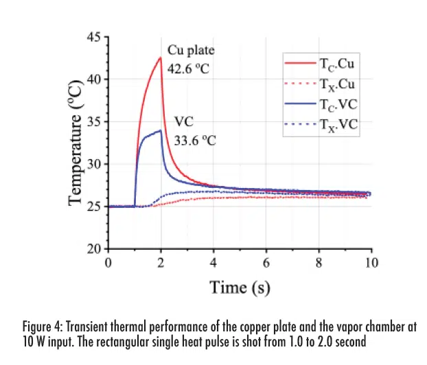
Figure 4 shows a 1-second single rectangular heat pulse generated by the laser. The temperatures of both a VC and a copper plate are measured for comparison, for a dissipation of 10 W, which is greater than Qmax. The maximum TC occurs during the falling edge of the heat pulse. It is 9°C lower for the VC than the copper plate. TX rises slowly as the heat propagates away from the heated spot. TX increases faster in the vapor chamber than the copper plate because the heat propagation speed is faster by vapor convection than by copper thermal conduction. The measurements show that the vapor chamber is both a fast-acting and effective heat spreader, which is advantageous for handling transient thermal pulses or spikes. The transient dissipation can go beyond the steady-state Qmax limit under the proper power and time duration conditions, as confirmed in Fig. 4.
Conclusions
The non-contact measurement method for thin vapor chambers has the advantage of more accurate measurements using the laser heat source, faster measurement time, and the ability to measure transient characteristics. It has great potential for thin vapor chamber testing.
References
- G. Patankar, et al., A method for thermal performance characterization of ultrathin vapor chambers cooled by natural convection, Journal of Electronic Packaging, vol. 138, 010903, 2016.
- X. Jiang, et al., A non-contact thermal testing system for ultra-thin vapor chamber, Review of Scientific Instruments, vol. 92, 124902, 2021.
- K. Y. Hsu, et al., A Thermal Performance Characterization Method for Thin Vapor Chambers by Photonics Technologies, 40th Semiconductor Thermal Measurement, Modeling & Management Symposium (SEMI-THERM), San Jose, CA, USA, pp. 76-82, 2024. https://ieeexplore.ieee.org/document/10535014
- G. Patankar, et al., On the transient thermal response of thin vapor chamber heat spreaders: Governing mechanisms and performance relative to metal spreaders, International Journal of Heat and Mass Transfer, vol. 136, pp. 995-1005, 2019.


