Introduction
Thermal management of servers and communications equipment has become significantly more challenging over the past several years. As is well known, processor powers have increased to 150 W or more and are projected to continue to rise, despite the move to multi-core designs (and the huge investment in software that this entails) [1]. Rack-level functional density continues to be a significant competitive advantage for those companies able to harness the latest semiconductor technology � which only exacerbates the cooling problem. A recent ElectronicsCooling article highlighted the most recent front in thermal management � reducing the cost and increasing the efficiency of data center cooling [2].
Forced-air heat sinks have become significantly larger, more expensive, and more complex. As a consequence, liquid cooling is undergoing a renaissance at the device, rack, and data center levels. For device cooling, hybrid liquid-air cooling systems using single-phase water-based coolants and microchannel cold plates have been used in commercial systems [3, 4].
Another liquid-based cooling approach is explored in this article: two-phase refrigerant loops using meso-scale evaporative cold plates. In the work to be described, the refrigerant used was R134a. This approach allows considerable flexibility in the configuration of systems and the choice of materials, while maintaining very high heat transfer performance. An added benefit is that a number of cold plates can be connected in series, since the evaporating fluid remains at the local saturation temperature, and scaling to the data center level is possible [5].
Two-Phase Hybrid Device Cooling
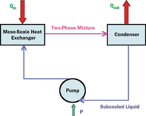
Figure 1 illustrates two-phase device cooling using meso-scale cold plates (solid-to-fluid heat exchangers). We have chosen the term “meso-scale” because our designs span the micro- and minichannel regimes. Microchannels are conventionally defined as channels with hydraulic diameters in the range from 10 to 200 �m, while minichannels extend from 200 �m to 3 mm.
 |
Figure 1. Two-phase hybrid device cooling.
There are three important components in this simplified design: the pump, the condenser, and the meso-scale cold plate. Heat is absorbed in the cold plate, with the working fluid entering at saturation conditions and exiting with some non-zero quality xe less than 100%. Note: Exit quality is defined as the mass flow of vapor divided by the total mass flow at the exit of the cold plate. The two-phase mixture travels to the condenser, which can be close to the heat source or far removed. Finally, the liquid is pumped back to the evaporator to begin the cycle again.
Typical Cold Plate Design Requirements
An example thermal resistance budget for a model microprocessor is
Rtot = Rds + Rsf + Rfa (1)
where the total thermal resistance Rtot is the sum of the die-to-sink, sink-to-fluid, and fluid-to-ambient resistances. For a nominal 200W load, the total resistance should be less than 0.3 K/W (assuming a 40�C ambient temperature and 100�C maximum die temperature).
Typically, the die-to-sink resistance, inclusive of all thermal interfaces, is about 0.15 K/W. Thus, the sum of the cold plate resistance Rsf and the condenser thermal resistance Rfa must be less than 0.15 K/W.
While the condenser resistance can be made very low providing enough space and/or airflow is available, arbitrarily assuming a 50-50 split between the condenser and the cold plate usually results in a reasonably sensible design. Thus, a cold plate resistance of 0.075 K/W should be adequate for a 200 W load. As will be seen in the experimental results presented in this article, this requirement is readily met and in fact can be significantly exceeded.
Two-Phase Meso-Scale Cold Plate Experiments
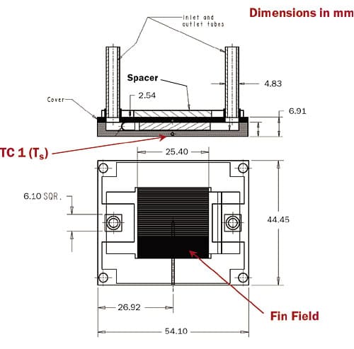
In order to illustrate the feasibility of obtaining such thermal resistances, we have conducted a series of experiments exploring an appropriate design space. The tested cold plate structure is illustrated in Figure 2.
 |
Figure 2. Cold plate dimensions.
The material used for the experimental cold plates was brazed oxygen-free high conductivity (OFHC) copper; the internal channels were formed using a folded fin pack design. For the experiments, the heat source size was fixed at 2.2 cm (0.86″) square. The channel height was 3.05 mm (0.12″).
In the current experiments, fin density varied from 3.9 fins per mm to 7.9 fins per mm (100 to 200 fins per inch) and the fin thickness from 0.05 to 0.15 mm (0.002″ to 0.006″). This resulted in channel hydraulic diameters (Dh) that ranged from 0.1 to 0.4 mm.
For the experiments, the R134a liquid flowrate was varied between 126 ml/min (2 gph) to 315 ml/min (5 gph). Finally, heat loads of 100, 200, 300 and 400W were applied.
The experimental apparatus has been described previously [6]. Care was taken to achieve zero subcooling on entry to the cold plates.
Experimental Results
The three primary variables under investigation were (a) flowrate, (b) heat flux, and (c) cold plate geometry. Note that the results to follow are based on the cold plate thermal resistance as defined by
Rsf = (Tbase-Tsat)/Q (2)
where Tsat is the saturation temperature of the fluid. The base temperature is measured by an embedded thermocouple that is located ~0.9 mm (0.03″) below the plane of the fins (TC1 in Figure 2) � therefore, the measured Rsf includes a conduction resistance that turns out to be ~ 0.009 K/W.
Thermal Resistance and Pressure Drop vs. Flowrate
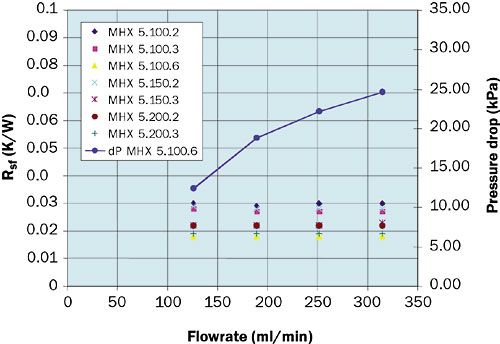
Figure 3 below shows the experimental results for Rsf and pressure drop vs. flowrate at a heat load of 200 W. The data is coded as follows: “MHX 5.100.6″ is a cold plate with 100 0.006” thick fins per inch.
 |
Figure 3. Rsf and pressure drop vs. flowrate.
All of the test cold plates provide excellent thermal performance, exceeding the 0.075 K/W thermal resistance goal by at least a factor of 2. Exit quality varied between 17% and 42% for these tests.
Interestingly, thermal performance is essentially independent of flowrate in this range. In flow boiling, the heat transfer coefficient is a complex function of geometry, flowrate, and local quality (see, for example, reference [7]). The average h along the length of the channels apparently does not vary significantly in our chosen operating range.
Thermal Resistance vs. Base Heat Flux
Of some interest is the variation in thermal resistance with base heat flux (i.e., the heat load divided by the “chip” area). As with the flowrate, there is very little variation of thermal resistance with base heat flux in this range of operation. Using conventional flow boiling correlations, the heat transfer coefficient is proportional to the 1/3 power of the local heat flux, but the fin efficiency decreases with h, so that the net effect (again, in the chosen operating range) is negligible. Fin efficiencies in these tests were in the range 30% – 50%.
The heat source size in these experiments was 2.2 x 2.2 cm, corresponding to an actual very-high-power microprocessor application. The experimental setup used heat fluxes limited to ~ 100 W/cm2. Other tests, using a cold plate with 1.9 fins per mm and 0.20 mm thick fins, have been run with heat fluxes from 250 to 1000 W/cm2 using a 1 cm x 1 cm source; these results showed slightly decreasing Rsv with heat flux.
Performance Prediction and Optimization
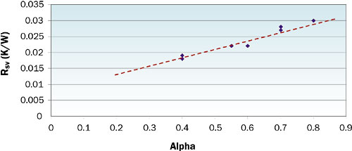
While the basic cold plate construction outlined above has been used for a variety of applications (including significantly larger and smaller heat sources, as well as for multiple-source applications), the data presented here is limited to an exploration of fin density and thickness with other dimensions and materials being fixed. Given this limitation, the Rsf test data was replotted as a function of α (the ratio of open face area to total face area). This is a typical approach used in heat exchanger design. The results are shown in Figure 4.
 |
Figure 4. Rsf vs. α (Q = 200W; flowrate = 252 ml/min).
The data are well behaved and allow prediction of performance for other designs with similar geometries. Of note is the observation that designs of quite different combinations of fin density and thickness will yield similar results.
Extrapolation of these results to cold plates of significantly different feature sizes, of course, is more complicated. A design correlation is being developed.
Conclusion
Meso-scale evaporative cold plates using R134a as the working fluid are capable of achieving very low thermal resistances, effectively removing the heat sink as a limit to chip-level thermal management. Moreover, devices with hydraulic diameters as low as 0.1 mm can be fabricated without resorting to complex and expensive semiconductor fabrication techniques.
While the flow boiling and two-phase fluid mechanics in these devices is exceedingly complex, over the range of parameters and operating conditions described in this article, the thermal resistances vary little with either flowrate or heat flux, which is a benefit to cooling system design.
References
- International Technology Roadmap for Semiconductors (ITRS), 2005.
- Belady, C., “In the Data Center, Power and Cooling Costs More than the Equipment It Supports,” ElectronicsCooling 13 (1), February 2007.
- “Apple Launches Liquid Cooled G5 Mac,” http://www.theregister.co.uk/2004/06/09/apple_g5_update/, June 2004.
- “HP Launches Water-Cooled Opteron Systems,” http://www.theinquirer.net/default.aspx?article=37378, February 2007.
- Hannemann, R. and Chu, H., “Analysis of Alternative Data Center Cooling Approaches,” InterPACK paper 1176, InterPACK ’07, Vancouver, BC, July 2007.
- Hannemann, R., Marsala, J., and Pitasi, M., “Thermal Design and Performance of Two-Phase Mesoscale Heat Exchangers,” paper HT2005-72743, National Heat Transfer Conference, San Francisco, July 2005.
- Bontemps, A., Agostini, B., and Caney, N., “Flow Boiling in Minichannels,” Microscale Heat Transfer, Springer, Dortrecht, 2004, pp. 217-230.


