Vapor compression refrigeration has long been used to cool telecommunications equipment and some high performance computers. On the whole, however, its usage has been confined to high-value, relatively large, and stationary applications. The advantages of vapor compression cooling (VCC) systems are fairly well known. They can provide heat sinks at below ambient temperatures [1], remove large amounts of heat using relatively low power, and can protect electronic components from overheating. Additionally, at low temperature, reliability improves and microprocessors run at faster speeds. Historically, though, VCC systems have had difficulty fitting within the space limitations of a small electronics chassis [2]. The challenge has been to create a small but powerful enough system for electronics systems.
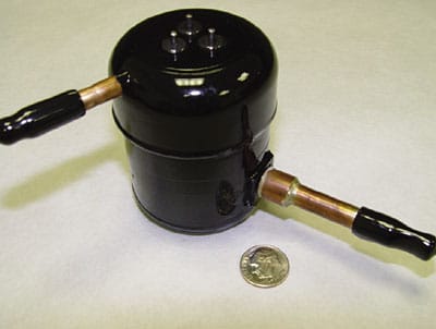 |
Figure 1. Miniature refrigeration compressor.
A major obstacle to building small VCC systems was the absence of commercially available and affordable miniature refrigeration compressors in the fractional-kilowatt range that would fit within a small space. Recently, such a compressor (measuring only 5.6 cm in diameter x 7.6 cm high and weighing only 630 g) has been developed and become available [3]. A photograph of the mini -compressor is shown in Figure 1. The compressor is a rotary design with a rolling piston driven by a sensorless brushless DC motor running at 24 VDC.
Table 1. Design Specification for ECU [3].
|
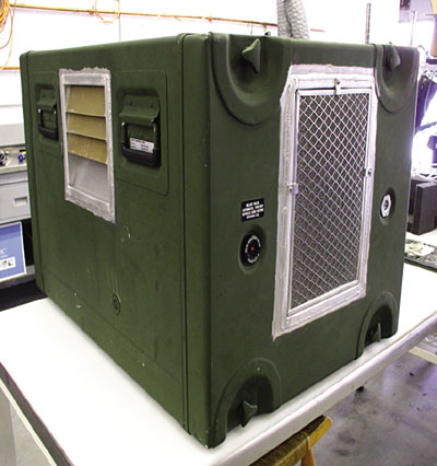
The use of this compressor was recently evaluated in an application that had been using a rather large thermoelectric cooler (TEC) in a mobile satellite antenna electronics case for the U.S. Army. The TEC unit positioned on top of the case weighed 25 kg, necessitating a separate transport case for moving, and providing insufficient cooling capacity in many operating conditions. Utilizing the miniature compressor, a compact VCC Electronics Cooling Unit (ECU) system that can slide into a standard 48 cm wide and 2U high electronics rack was developed as shown in Figure 2. The specifications for the 2U rack- mounted ECU is shown in Table 1. The replacement 2U rack-mounted ECU was to deliver 500 W (J/s) of cooling and 800 W (J/s) of heating to satisfy the requirements in all operating conditions. Figure 3 shows the same antenna electronics case with the new VCC system mounted inside.
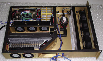 |
Figure 2. 2U rack mountable VCC refrigeration system incorporating new miniature compressor.
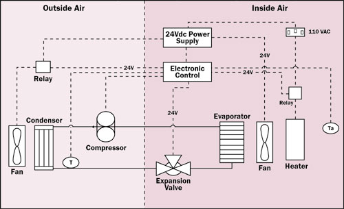
The ECU was designed as a sealed forced air system, where the outside airstream for the condensor was isolated from the recirculating inside air to cool the electronics components. The vapor compression cooling system layout is shown in Figure 4. In addition to the miniature refrigeration compressor, it consists of the following custom and off-the-shelf components: evaporator heat exchanger, condenser heat exchanger, power supply, relays, fans, heater, and mounting board.
Figure 3. Mobile satellite antenna electronics case with rack mounted cooling system inside.
Figure 4. Layout of refrigeration components for ECU.
Due to space limitations, the design also employed other high performance components including custom designed evaporator and condenser heat exchangers. In order to keep the condenser’s heat transfer surfaces clean from airborne particulates, an air filter was included in the sealed air system. The satellite communications unit was intended for use in outdoor environments with wide ranging ambient temperatures, severe dust, driving rain and other severe and stringent conditions required for military operation.
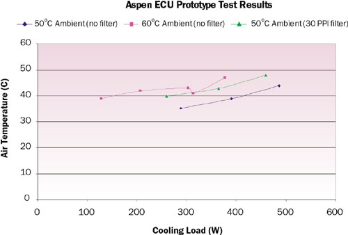 |
Figure 5. Cooling load versus ambient temperature [4].
A battery of tests were performed under simulated conditions to evaluate the performance of the antenna electronics case of the new unit. Figure 5 illustrates some of the thermal load measurements taken during these tests, which ranged from just over 100 W to just under 500 W. Although the data shows lower performance with the air filter in place as expected, the cooling system still provided adequate cooling to maintain the electronics case at safe temperatures.
A separate set of tests was also conducted to simulate the severe outdoor conditions of a desert environment. The testing subjected the electronics equipment case to an ambient temperature of 50�C and 1,000 W/m2 solar radiation, and was intended to represent the most stringent conditions on the earth’s surface. Those tests performed for the Army demonstrated that the VC cooling system could maintain the electronic components within safe operating temperatures, even in the harshest conditions.
Table 2. Performance Comparison VC and TE Cooling in SatCom Transit Case.
|
* Data shown includes VC Cooling Unit and separate Resistance Heating Unit
The vapor compression cooling unit designed for this project was substantially smaller and lighter than the legacy system, a thermoelectric cooler (TEC) that it replaced. As shown in Table 2, the cooling capacity of the VCC unit was higher than the TEC unit (500 vs. 350 W), and its coefficient of performance (COP) was substantially higher (2.94 vs. 0.32). One of the key performance parameters in an electronics cooling application is the power density, or cooling capacity per unit volume or per unit weight. As shown in Table 2, the power density of the VCC unit on either a weight or volume basis is excellent.
Refrigeration-based cooling is reliable and has been proven over many decades of use. It can handle high heat loads with a high COP. What has been demonstrated [5] here is a robust miniaturized refrigeration system, having a unique size to fit a 2U rack with a cooling capacity of 500 watts. Although long term reliability has not yet been demonstrated, it can be concluded that a compact and rugged VC cooling system can protect microelectronics, even in severe military environments.
References
- Peeples, J., “Vapor Compression Cooling for High Performance Applications,” ElectronicsCooling, Vol. 7, No. 3, August 2001.
- Mongia, R., Masahiro, K., DiStefano, E., Barry, J., Chen, W., Izenson, M., Possamai, F., Zimmermann, A., Mochizuki, M., “Small Scale Refrigeration System for Electronics Cooling within a Notebook Computer,” Tenth Intersociety Conference on Thermal and Thermomechanical Phenomena in Electronics Systems, 2006. ITHERM, May 30 – June 2, 2006, pp. 751 – 758.
- http://www.aspencompressor.com/technical.htm
- Leasure, S., “Testing and Evaluation of the Environmental Control Unit Prototype (TEECUP) Project,” Final Technical Report, Prepared for Naval Air Station Jacksonville, Concurrent Technologies Corporation, December 2005.
- Membrino, T., “Prototype Vapor Cycle Air Conditioner,” Phase 1 Final Report for Concurrent Technologies Corporation, June 2005.

