Introduction
As most readers of ElectronicsCooling magazine are no doubt aware, fins may be added to a heat transfer surface to increase the effective heat transfer area and thereby reduce the base surface temperature for a given heat load and heat transfer coefficient. The formula to estimate the heat dissipation capability, qf, of a straight fin is given by,
 |
and Af is the fin surface area, Lf the fin length, tf the fin thickness, kf the fin thermal conductivity, Tbase is the fin base temperature and Tamb is the temperature of the cooling medium. In the derivation of this formula, which may be found in many heat transfer textbooks, the fin heat transfer coefficient is assumed to be a constant [1]. While this may be a valid assumption for single-phase heat transfer it is certainly not valid for two-phase heat transfer processes such as pool boiling. Pool and flow boiling have for a long time been considered to offer an effective method for cooling high heat flux electronic components [2]. These processes offer high heat transfer coefficients, but these heat transfer coefficients and their associated heat flux are a function of the temperature difference, ΔTsat (also called wall superheat), between the heated surface and the saturation temperature of the boiling fluid as shown in equation (2).
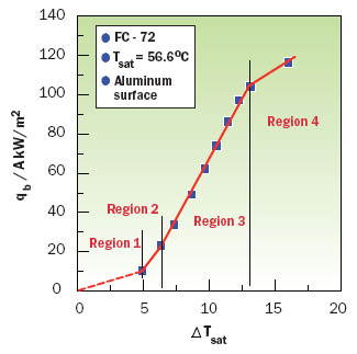
The variation in heat flux with wall superheat for pool boiling off a rough aluminum surface in FC-72 is vividly shown in Figure 1 [3]. For example at a ΔTsat of about 5�C the heat transfer coefficient is about 2200 W/m2-K and at a ΔTsat of about 13�C the heat transfer coefficient is about 8000 W/m2-K. To effectively estimate the performance of a boiling fin it is clearly necessary to take into account the variation of heat transfer coefficient or boiling heat flux with ΔTsat along the length of the fin.
Calculation Procedure
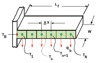
The remainder of this article will describe a simple procedure to estimate boiling fin performance using the geometry and model nomenclature illustrated in Figure 2. As shown in Figure 2, a straight fin of uniform thickness tf, thermal conductivity kf, length Lf and width W is divided into N equally spaced nodes so that the distance between each node is Δx or Lf/N. Accordingly the cross-sectional fin area for thermal conduction between each node is W�tf or Acond. Similarly, the surface area for boiling heat transfer from each node (neglecting the edge surfaces) is 2�Δx�W or Ab. For purposes of illustration the boiling heat flux from each node was calculated based upon the boiling curve shown in Figure 1. To represent the relation between heat flux, qb/A, and ΔTsat a four segment piecewise continuous linear curve with each segment given by
was faired through the data points as shown in Figure 1.
 |
Figure 1. FC-72 boiling curve data (adapted from Geisler and Bar-Cohen [3]).
Figure 2. Boiling fin geometry and model nomenclature.
Table 1. Boiling Curve Coefficients.
|
The coefficients C0 and C1 for each segment or region are shown in Table 1. The amount of heat transferred by boiling from an individual node is given by,
The calculation procedure is initiated by assuming a fin tip temperature, TN, at the rightmost node. The heat transferred from this node to the fluid by boiling, qbN , is calculated using (4). Using TN and qbN it is then possible to start “marching” back along the fin progressively calculating each nodal temperature and the amount of heat transferred by boiling from each node. The temperature of each successive node is calculated using
 |
Finally the temperature at the base of the fin is calculated using
 |
and the total quantity of heat dissipated by the fin is calculated using
 |
The calculation scheme used is further illustrated by the sequence of steps shown in Table 2. It should be noted that for the sake of simplification, the steps to determine which region of the boiling curve a particular node is operating in (in order to choose the appropriate coefficients from Table 1) have been omitted from the sequence.
Table 2. Sample Code for Temperature Calculation
|
As many readers may appreciate, this calculation scheme may be readily coded using programming languages such as BASIC or C, or mathematical analysis software with looping capability.
To determine the fin heat dissipation capability for a specific fin base temperature (or vice versa) it is necessary to repeat the calculation process several times with a different fin tip starting temperature each time. The resulting values of fin heat dissipation and fin base temperature may be plotted against each other to generate a curve with which to interpolate intermediate values of either quantity. Alternatively, a scheme may be incorporated into the program to select new starting fin temperatures each time to automatically close in on a specified value of either fin heat dissipation or base temperature. In either case, it should be noted that in some cases small changes in fin tip temperature (tenths of a �C or less) can result in substantial changes in total fin heat dissipation. The possibility of this behavior should be taken into account in whichever of the above methods is used. Because of the sensitivity of heat flux qb/Ab to ΔTsat it is advisable to use a many nodes as practical. For the calculations described in the following section the author used over 1000 nodes. In many cases it may be possible to get good results using fewer nodes, but the user is well advised to investigate the sensitivity of the results to the number of nodes used.
 |
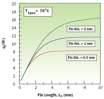
Figure 3. Effects of fin thickness and length on fin heat dissipation capability for a base temperature of 70�C.
Example Results
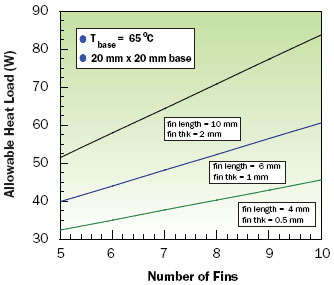
Two sets of calculations were performed to illustrate applications of this method to estimate boiling fin performance for a 20 mm wide aluminum fin in a saturated pool of FC-72. The first set of results, shown in Figure 3, illustrates the effects of fin length and fin thickness on total fin heat dissipation capability as a function of fin length for fin thicknesses of 0.5, 1, and 2 mm respectively. The second set of results shown in Figure 4, illustrates the allowable heat sink heat load versus the number of fins on a 20 mm x 20 mm base for each of the previous fin thicknesses with fin lengths of 4, 6 and 10 mm respectively. The values of allowable heat load include both the heat dissipated by the fins and the heat dissipated by the exposed portion of the base at a base temperature of 65�C. The amount of heat transferred by the exposed portions of the base (i.e., between the fins) was estimated using equation (4) with T equal to 65�C and area Ab equal to the exposed base area. Using the same equation it is estimated that the base area alone without fins could support a heat load of about 19.6 W. Comparing this allowable heat load with the values shown in Figure 4 clearly indicates the potential of a boiling heat sink, even with very short fins, to substantially increase the total heat dissipation capability.
 |
Figure 4. Effect of number of fins on total heat sink dissipation capability for a base temperature of 65�C.
References
- Incropera, F.P., “Fundamentals of Heat and Mass Transfer,” John Wiley and Sons, New York, NY, 1985.
- Simons, R.E., “Direct Liquid Immersion Cooling for High Power Density Microelectronics,” ElectronicsCooling, Vol. 2, No. 2, May 1996.
- Geisler, K. J. L., and Bar-Cohen, A., “Optimization of Pool Boiling Heat Sinks Including the Effects of Confinement in the Interfin Spaces,” Proceedings of IPACK ’07, IPACK2007-33620, Vancouver, BC, Canada, 2007.


