Introduction
The performance of electronics cooling fans has been steadily increasing as flow requirements chase higher thermal loading. These advances have been primarily achieved through mechanical and architecture changes. However, the aerodynamic sophistication of these fans has progressed to a lesser degree, and is far removed from turbomachines used in higher power density applications such as gas compressors and propulsion fans. If you will, cooling fans are most often “children of a lesser effort” aerodynamically speaking. Although there are differences in the dominant flow physics, there is no fundamental limitation to improving cooling fan aerodynamics to the level of sophistication enjoyed by their larger cousins.
Motivation
The benefits of employing an advanced aerodynamic design are tempting. Consider, for example, a fan with a baseline aerodynamic (total-static) efficiency of ηa=30% driven by a motor with efficiency ηm= 75%. Increasing the aerodynamic efficiency by 10 points (i.e., from 30% to 40%) results in a 33% gain in overall efficiency (ηo=ηa ηm). In contrast, improving the motor efficiency by a similar amount would only result in a 13% gain. The reason for this is quite simple; the figure of aerodynamic merit (static efficiency) is typically much less than the motor efficiency. Perhaps more importantly, increasing motor efficiency usually translates into more expensive components- but a better aero design can often be implemented with little part-cost impact.
The above exercise would be purely academic if achieving a 10% increase in motor efficiency was realistic and achieving a similar level in aerodynamic efficiency was not. But the truth is that aerodynamic gains of this order are achievable. Aircraft engine core compression technologies have seen improvements of this magnitude from the beginning of the jet age (e.g., Jumo 004) to today’s advanced engines (e.g., GE90). Significantly, the aerodynamics of most current generation cooling fans is closer in lineage to the earlier example than to the latter.
Advanced Aerodynamics
Without delving into the “how” of fan design, a simple explanation of what is meant by “advanced aerodynamics” is perhaps best expressed in terms of a design goal. A superior aerodynamic design achieves a target pressure rise with minimum excess kinetic energy. Excess kinetic energy is the primary loss driver in a fan system, and minimizing it is basically a matter of optimizing the aerodynamic diffusion in the system. That is, optimizing the reduction of rotating-frame-relative velocity in the impeller and the absolute (fixed-frame) velocity across vanes, struts, and through the fan duct.
Such aerodynamic sophistication can occasionally be stumbled upon by experimental optimization, but to do so routinely requires a progressive-dimensionality design system and the expertise to use it. Such design approaches are commonly employed by gas-compressor design groups and more rarely found in companies focused on lower power density blowers and fans. Although Computational Fluid Dynamics (CFD) tools are often thought of as the key to advanced designs, they are best employed only in the final refinement of the flow path. The key to optimized aerodynamics are the lower-order (e.g., 1D, 2D, and quasi-3D) tools that precede CFD analysis. In fact, in many cases experimental prototyping can be more cost effective than CFD if the underlying design tools and rules are robust.
What you gain by this effort, as expressed above, is lower power draw compared to a more conventional fan. Or, for the same power draw, more flow and/or pressure delivery. Other advantages manifest themselves. A design with more sophisticated aerodynamics can achieve a performance target at reduced speed, driving both reliability and noise in favorable directions.
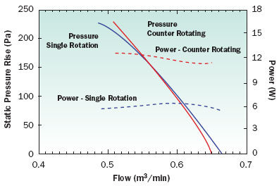
Architecture can also be impacted by the level of the aerodynamic design. Less control over aerodynamic diffusion can push the designer to move into a mixed or radial flow design when a properly designed axial flow fan could do the job more efficiently. Resorting to multiple stages or counter-rotating impellers can also compensate for weaker aerodynamics at the cost of complexity and efficiency. An example of this is shown in Figure 1, where a comparison is made between a single-rotation fan featuring advanced aerodynamics and a counter-rotating fan of identical space claim featuring less sophisticated aerodynamic design. At the same speed, the single-rotation fan achieves the same pressure vs. flow characteristic over the target operating range as the more complex counter-rotating fan. The power draw is, as expected, significantly reduced in the advanced-aero single-rotation fan.
Figure 1. A comparison of a counter-rotating fan and a single-rotation fan at similar speeds. The single rotation fan employs more advanced aerodynamics, allowing it to achieve similar pressure rise and lower power draw than the more complex counter-rotating fan.
This example should not suggest that architecture and aerodynamics are mutually exclusive; there is no impediment to employing better aero design practices in any architecture be it impeller-only, vane -axial, or counter-rotating. What it does demonstrate is that the pressure levels gained by more complicated architecture can often be matched by simply refining the aerodynamics, with an efficiency benefit. The magnitude of the efficiency benefit will of course vary with the limitations set by the drive line and space claim.
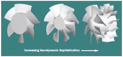
Recognizing a fan with such aerodynamic refinement is best done by observing the improved performance, as the geometric differences can be misleading. Typically, an advanced impeller will have a more “3-D” appearance than a more two-dimensional classic design, as shown in Figure 2. However, there are examples of quite “artistic” impeller shapes that have more to do with marketing than efficiency. If the space claim permits, such an impeller can be followed by vanes and/or ducting designed to manage the kinetic energy downstream, Figure 2, or a second rotor in a counter-rotating design. Again, the bottom line for the application engineer should be a demonstration of class-leading performance.
 |
Figure 2. Example of a conventional impeller (left) and a similar impeller with high efficiency aerodynamics (center) . Space permitting, the impeller can be followed by a vane row to further reduce excess kinetic energy (right).
Conclusion
As the most basic function of a fan is to convert shaft work to flow energy, it is not surprising that such a broad range of benefits can be gained by optimizing that conversion process. Several vendors have begun to introduce fans which feature aspects of advanced aerodynamic design, and this trend will continue as design systems mature. The application engineer should recognize, however, that any fixed-geometry fan has a single peak efficiency point. Failing to match the system impedance to the fans high-efficiency operating range will degrade the best aerodynamics.


