Introduction
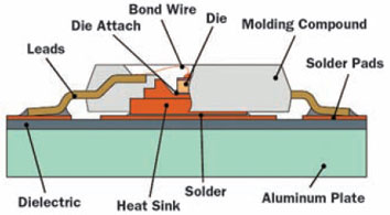
The main topic of the article is how to cope with the increasing need for standardization of thermal characterization of LEDs (Light Emitting Diodes) and LED-based products (see Fig.1 showing a typical LED package). The LED-business is growing much faster than analysts predicted five years ago. Unfortunately, the progress in thermal characterization has not kept pace. Due to the lack of worldwide accepted standards a manufacturer can publish whatever thermal information he wants. It also becomes a problem for the experienced user because the published thermal data are questionable when accuracy is needed for an educated guess of expected performance and lifetime. Remarkably, the situation is not much different from the one the IC-world was facing almost 20 years ago.
 Figure 1. Sketch of a typical power LED package.
Note: this article is essentially a summary of two recent papers on LED standardization [1,2].
Determining Critical Temperatures in Practice
An end-user wants to calculate some critical temperature (usually the junction temperature, but often also a solder joint temperature). The equation that is mostly used is:
Tjunction = Rth j-ref � P + Tref (1)
Rth j-ref is a number that is supplied by the manufacturer, the power P is usually supplied by the electronic engineer, and Tref is a reference temperature that depends on the definition. After Tjunction has been calculated, this temperature is usually compared to a specified temperature. When Tjunction is higher than Tspecification, chances are high that a redesign is requested. Obviously, one should be convinced about the accuracy of the calculated Tjunction before jumping to such a decision.
Equation (1) looks like a very simple equation, but there are many questions that could be asked questioning its accuracy. For example:
- How is Tjunction defined? Can it be measured in practice? If not, how to derive it from another measurement, for example Tcase?
- What is Tref? Can it be unambiguously defined? Is it easily measurable in practice?
- How is P defined? Corrected for non-thermal contributions?
- What is the physical meaning of the thermal resistance used in the equation?
- Is the thermal resistance used in the equation really temperature independent?
- What is the variance in the published data per manufacturer?
Exactly because of the many uncertainties that make equation (1) much more complex than designers think, it is possible to quote almost any value. This is the main reason for the need of worldwide standardization. However, standardization of some agreed metric as such is not sufficient. In the IC world, it appeared that the drivers for thermal characterization are quite different for manufacturers and their customers, and this situation is not very different in the LED world. It turned out that these differences were the major cause of the ‘Babylonic’ situation the IC world was facing about 20 years ago, and the LED world could profit from the lessons learned. The reader interested in IC thermal standards is referred to the JEDEC website [3].
A major breakthrough in IC thermal characterization emerging from the DELPHI project [4] was the notion that we needed a boundary between the responsibilities of the manufacturers and the end-users:
- The manufacturer is responsible for the thermal model of the part and nothing else.
- The end user is responsible for the specification of the thermal environment to which the part is exposed.
The consequence of this partition between responsibilities was that we needed a new way of thermal characterization, coined ‘Boundary Condition Independent Compact Thermal Modelling’. In short, the manufacturer should publish thermal data in such a way that the end-user could use these data for whatever application the component is intended. This philosophy is currently underlying a number of JEDEC documents [5].
Unlike two decades ago in the IC world, Tjunction of an LED is not just a performance indicator of the thermal design but plays also a major role in lighting design since all properties of the light output of an LED depend on the absolute junction temperature. This means that Eq. (1) is now an integral part of the overall design of an LED based lighting solution, resulting in changing roles of different engineering disciplines in the overall design process. The design of electrical and thermal conditions cannot be 100% decoupled as is the case in classical electronic circuit design. More information about thermal aspects of LEDs can be found in [6,7].
Goals of LED Thermal Characterization: Reliability and Performance Prediction
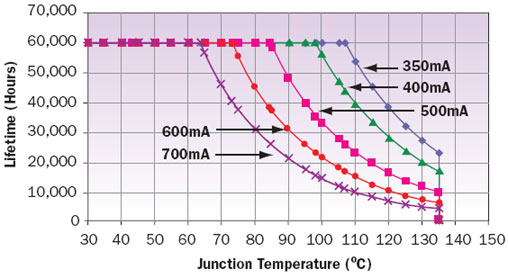
The most important reason for an LED designer to use thermal data is to estimate the junction temperature upon which to base any assessment of the reliability and performance of the final product. The main temperature-related problem at the device level is reduction in light output as a function of time. Because of this phenomenon, the light output may decrease to an unacceptable level before a ‘real’ irreversible failure occurs. This condition may be coined a ‘lumen maintenance’ failure. The level at which this is called a ‘failure’ should be subject to standardization.
Figure 2 shows an example of how Lumileds presents its reliability data. The Figure shows the expected lifetimes for the junction temperature at 90% confidence interval, where B50 is the time by which 50% of the population is expected to fail, and L70 means that any product with more than 30% light output degradation is classified as a failure.
 Figure 2. Expected (B50, L70) lifetimes for a state-of-the-art AlInGaP LED.
Needless to say, that all these parameters are subject to standardization because the average customer will get lost if one manufacturer quotes reliability in terms of B50, L70 and another in terms of B10, L50.
Drawbacks of Current Thermal Data Sheets
About the most important things a designer of an LED-based product wants to know are luminous flux (lumen) and efficacy (lumen/W), not only at zero hour but also over its expected lifetime. Problems with current data sheets are:
- Data sheets do not reflect real-life operation, especially regarding operating temperature.
- They differ strongly in content (Tref, Iref). Often Tjunction specified at 25�C, which is misleading, because the efficacy at maximum rated power is often 50% lower than at room temperature. On the positive side, leading manufacturers have started to quote more realistic values.
- Often a direct comparison between manufacturers is not possible.
- While non-thermal but temperature-related: the translation to useful lumens or non-nominal use is not an easy task even for experienced designers.
- The way of quoting thermal data by manufacturers is the series thermal resistance approach, which is questionable in a number of practical cases for which more complex thermal networks are preferred.
Let us focus for a moment on the definition of power and the series resistance approach.
The Definition of Power
Maybe the biggest problem today hampering a fair comparison is the lack of a standardized way of defining power. Many manufacturers define their power dissipation by the product of voltage and current, not taking into account the efficiency of the conversion from electricity into light.
In our view, any thermal resistance should only be related to the physical properties and the dimensions, and should be independent of the efficiency. The problem in practice is that the user should know the efficiency along with the total dissipated power. On the other hand, quoting a better efficiency is an important sales argument with the increasing interest in sustainability, and hence it makes sense to decouple this parameter from the physical Rth.
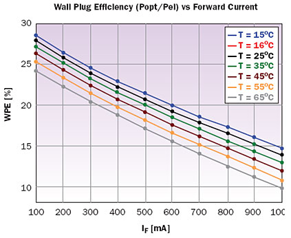
As shown in Figure 3, the overall efficiency (also known as wall plug efficiency (WPE), which is Poptical/Pelectrical) depends on temperature and current. That is why any metric of an LED reported in a data sheet should also be reported together with the current and temperature at which the given metric was identified.
 Figure 3. Current and temperature dependence of the WPE of a red Dragon LED (measured by MicReD).
The Series-Resistance Approach
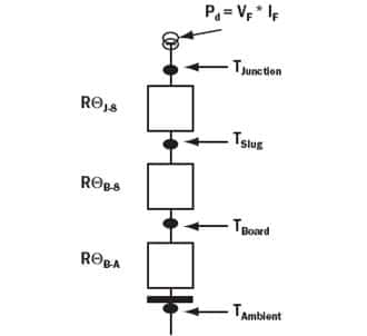
In principle, a series thermal resistance approach (Figure 4) can never result in a boundary condition independent thermal model because spreading resistances depend on the boundary condition [8]. In theory, such a network is only correct for the boundary conditions used for the test in question. In practice, there are exceptions. For many high-power LEDs the lateral temperature gradients can be neglected. In these cases it can be shown that the series resistance approach is valid. It should be noted that a correct value of some resistances in the chain is not mandatory in all cases because these resistances may not be dominant in a real application. Often it turns out that the resistance to ambient is dominating, hence, errors in the published data are not critical. In summary, while it may be argued that especially for high-power LEDs the series resistance approach does describe the physics correctly, it is also true that we need thermal standardization protocols to address the accuracy of the series resistance approach for every possible application.
 Figure 4. Typical example of series resistance network from die to ambient.
Measurement Challenges
Apart from the lack of a standard way of defining power and accurate thermal data, measurements also pose a challenge. Some issues are:
- Die temperature is not unique.
- Phosphor-encapsulated dice pose extra problems, caused by absorption of light resulting in an extra heat source away from the junction.
- How to measure the outgoing light energy in order to calculate the thermal power?
- How to measure the case temperature? Our opinion is that power LEDs must be characterized on a cold-plate. Then, though we do not have the case temperature itself, we have quite accurate information about the cold-plate temperature. The standard should address thermal interface issues.
- How to tackle multi-sources? We propose to use a matrix representation for all sources. However, this is only feasible when access to every individual LED chip is provided � i.e. if the LED based system was also designed for thermal testability.
- What are the pros and cons of steady state vs. transient measurements?
- In production testing, properties of LEDs are measured by short pulses. How to relate the short pulse results to properties that can be measured under steady-state operating conditions without knowing details of the complex LED behavior?
Other Questions Regarding LED Thermal Standardization
Before trying to improve the data sheets and the test protocols, the following questions should be answered:
- What is needed in terms of standards and guidelines?
- What do the manufacturers want as a fair and reliable metric to compare products?
- What do (trained) end-users want, and can this be realized by the manufacturers?
- What about a purely numerical approach after suitable calibration?
- What links would be required with other international standardization or national measurement laboratories?
Only when we have addressed these issues does it make sense to start thinking about standardization. There are two considerations that mitigate the problems compared to the situation we faced 20 years ago with IC packages: from a thermal point of view LEDs are a lot less complex, and we have all the experience from the past including many standardization templates. On the other hand, it might turn out that thermal-only models are not sufficient for LEDs, and electro-thermal-optical multi-domain models may be preferred.
Proposal for Action
According to the authors, the logical choice for the standardization body is JEDEC because ICs and LEDs have many things in common. While for IC packages we decided to start with end-users only, it seems a better option from a timely point of view to establish a consortium consisting of all parties involved: end-users, LED manufacturers, system manufacturers (luminaries), software developers and test equipment manufacturers.
Conclusions
Let us summarize the main lines of thought discussed in the article.
- Without standards, manufacturers who cannot resist resorting to deceit have a competitive edge, creating a problem for the manufacturers who are at least willing to provide their customers with useful thermal data. The practice should be discouraged, not rewarded.
- When manufacturers do not take the initiative, end-users are going to demand reliable thermal data for their applications at some moment in time. The manufacturer who can provide these data in time has a competitive edge.
- LED thermal metrics are not only required for reliability and lifetime prediction but also for proper lighting design because all aspects of light output are highly temperature dependent.
- Accurate thermal modelling and testing requires dedicated expertise that is probably not available within the existing standardization bodies that focus mainly on electrical and optical standards where thermal is just an afterthought.
- The JEDEC JC15 thermal standardization committee is the logical choice to address the complex issues related to thermal modelling and testing standards.
- To define proper standards, manufacturers of components, systems, software and test equipment together with system designers should cooperate right from the start to gain precious time.
- Based on the successes in the past, it is worthwhile to check if an EU-funded European consortium could be initiated to address the scientific and technological challenges of LED thermal characterization and to prepare proposals for thermal standards.
References
- Poppe A., Lasance C., “On the Standardization of Thermal Characterization of LEDs,” Proc. 25th Semitherm, San Jose, March 2009.
- Lasance C., Poppe A., “Challenges in LED standardization,” Proc. 10th Eurosime, Delft, April 2009.
- www.jedec.com, in particular JESD51-12.
- Lasance C., “Ten Years of Boundary Condition Independent Compact Thermal Modeling of Electronic Parts: A Review, Heat Transfer Engineering,” Vol.29, pp. 149-168, 2008.
- JESD15-1 (CTM Overview) and JESD 15-4 (DELHPI CTM Guideline).
- Zhang L. and Treurniet T., “On the Challenges of Thermal Characterization of High-Power, High-Brightness LED Packages,” ElectronicsCooling, Vol. 14, No. 2, 2008.
- Petroski J., “Thermal Challenges In LED Cooling,” ElectronicsCooling, Vol. 12, No. 4, 2006.
- Lasance C., “Heat Spreading: Not a Trivial Issue,” ElectronicsCooling, Vol. 14, No. 2, 2008.


