Introduction
Cooling an electronics system involves transferring heat from various heat sources to the outside ambient. Thermal simulation software provides practitioners with predictions of the temperature and heat flux distributions in and around the system, making it easy to assess the impact of design changes. While the raw simulation results enable us to measure and visualize the thermal state of a design, they do not constitute a complete analytical toolkit. What is lacking is an understanding of the mechanics driving the observed temperature field and indications about where and how the design might be improved.
Heat transfer is highly 3-dimensional within an electronics system, resulting in many possible paths that heat could follow to the ambient. Some paths will carry a lot of heat and may also offer a relatively large resistance to the heat flow, characterized by a large temperature gradient, and so present a bottleneck. There will also be opportunities to introduce new heat flow paths (shortcuts) that circumvent such bottlenecks, thermally connecting hot areas of the design to locally cooler regions.
The goal of this article is to introduce and define two novel numbers1 derived as 3D field variables, computed as part of the thermal simulation, that taken together provide a way to decide where design improvements will have the most impact. This technical brief illustrates their use on a package-level example.
The BottleNeck Number
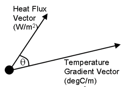
The dimensionalized BottleNeck (Bn) number is the dot product of the heat flux and temperature gradient vectors:
In vector notation: Bn = Heat Flux • Temperature Gradient
In scalar notation: Bn = |Heat Flux x Temperature Gradient
x cos(Θ) |
If the angle between the two vectors is zero, i.e., the heat flux is aligned with the temperature gradient as it would be for conductive heat flow in a homogenous thermally isotropic material, then Bn is the product of the magnitudes of the vectors, since cos(0°) =1 .
Large values of this Bn scalar, computed as a part of the thermal simulation, pinpoint areas of high heat flow experiencing a large local thermal resistance (characterized by a large, aligned temperature gradient), and thus identify the thermal bottlenecks in a design. Normalizing this scalar by the maximum value in a model will provide an indication of the relative levels of bottleneck in a single simulation model.

ShortCut Number
The dimensionalized ShortCut (Sc) number is also calculated from the heat flux and temperature gradient vector fields. The Sc scalar value at any point is calculated as the magnitude of the cross product of the two vector quantities.
In vector notation: Sc = Heat Flux x Temperature Gradient
In scalar notation: Sc = | Heat Flux x Temperature
Gradient x sin(Θ) |
If the temperature gradient is orthogonal to the heat flux,
then Sc is simply the product of the vector magnitudes, since
sin(90°) =1.
Large values of the Sc field pinpoint areas where large heat flux vectors are misaligned with large temperature gradient vectors (i.e., the heat is not moving directly toward a significantly cooler area), and thus identify locations where the benefit in establishing a new heat transfer path to shortcut the heat to colder areas of the design is highest. Normalizing this scalar by the maximum value in a model will provide an indication of the relative levels of shortcut opportunities in a single simulation model.
Illustrative Example
Electronics thermal simulations have always provided an indication of component junction and case temperature, information that can be used to judge thermal compliance by comparing the simulated temperatures against the maximum rated values. This is useful, but provides very little insight about why the temperature field is the way it is, and more importantly from a designer’s perspective, how and where to improve it.
To illustrate the Bn and Sc numbers in practice we have chosen a TO263 package mounted on a small test board in natural convection. The package is modelled in detail, with an isotropic trace layer included on the top of the board.
Thermal simulations can allow further insights into the heat removal paths by, for example, examining heat flux vectors. However, indications of the direction and magnitude of the heat flux vectors do not provide a measure of the ease by which the heat is leaving the system. Nor does it provide insight into where and how the heat flux distribution could be better balanced or re-configured to improve performance.
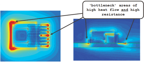
The Bn number is shown on a slice through the package symmetry plane, and in the top trace layer of the PCB in Figure 4.


The Bn field shows bottlenecks where the heat enters the top trace layer. Using these locations as a guide, the designer can then introduce targeted changes to relieve these bottlenecks and thereby reduce package temperatures. In this case, a solder pad on the PCB could be placed beyond the end and on the sides of the Cu-EFTEC-64T package tab, where the Bn field shows red in Figure 4.
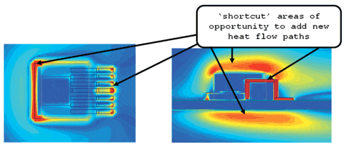
The Sc number exhibits non-zero values at the interfaces between materials, highlighting the areas where conduction shortcuts should start. Similarly, high Sc numbers in the air adjacent to a solid surface indicate regions where convective shortcuts should be considered, extending the surface area in contact with the air by introducing a heat sink.
The Sc field is shown on the same planes in Figure 5. High Sc numbers in the package tab at the tab-PCB interface indicate possible regions to insert thermal vias. High Sc numbers on the top of the package and on the underside of the board indicate regions of the air where heat transfer may be further enhanced through the addition of area-extending heatsinks.


Together the Bn and Sc fields offer tremendous insight into why the thermal performance of a design is what it is, and better, provide graphical information as to where the best opportunities for design improvement can be found. The Bn field provides clear identification of thermal bottlenecks and the Sc field indicates opportunities to introduce thermal shortcuts.
Unlike design-of-experiment methods, the Bn and Sc fields provide physical insight, helping both new and experienced thermal designers make targeted remedial thermal design modifications quickly and effectively. Application and interpretation of the Bn and Sc distributions within typical electronics design constraints offers a systematic methodology for determining the most promising thermal design modifications, by providing evidence beyond engineering intuition and experience where such modifications should be pursued.
1The descriptions of the BottleNeck (Bn) and ShortCut (Sc) numbers and their application to the post-processing of simulation data are proprietary and a patent is pending at the time of publication.


