Microelectronics and microsystems play a vital and increasingly important role in current and future human life and society. The future will bring a plethora of new products/processes based on new concepts with limited past experience to build upon. Much of the research of microstructures involves thermal management in one way or another, such as in relation to the biochemistry used in the domain of molecular diagnostics. Because of the complexity in both physics and geometry it is not to be expected that dedicated experiments may provide the required information in a timely manner. To get basic insight in the governing physics and to evaluate the consequences of many different layouts, numerical analysis is the only option. An additional advantage is that it often leads to new insights that may result in submitting valuable patents. This is called virtual prototyping, also known as simulation-based-design.
Lab-on-a-Chip systems
Micro-fluidic devices are at the heart of most biochip technologies, being used for both the preparation of fluidic (e.g. blood based) samples and their subsequent analysis. Such devices generally comprise small volume wells or reactors, in which (bio)chemical reactions are performed and the results examined. In the devices minute amounts of fluids must be rapidly and reliably regulated, transported, mixed and stored to carry out desired (bio)chemical reactions and analysis in large numbers. By carrying out assays in small volumes, significant savings can be achieved in time and the costs of targets, compounds and reagents. These devices are also called Lab-On-A-Chip (LOAC) systems. The LOAC concept generally consists of a disposable element that fits into a (universal) instrument to perform its function. Such a disposable element will need to be low-cost if large-scale disease or genomic testing is to become commonplace [1].

A specific example is Polymerase Chain Reaction (PCR). PCR can produce millions of identical copies of a specific DNA target sequence within a short time, thus has become a routinely used procedure in many diagnostic, environmental and forensic laboratories to identify and detect a specific gene sequence. This process achieves its amplification by 30-40 temperature cycles each of which consists of three temperature steps. The highest temperature is used to ‘de-nature’ the genomic DNA i.e. unwrap the double helix so that only single-stranded DNA exists. The second (low) temperature step is used to hybridize (or bond) a short probe molecule (e.g. 20 base pair length of DNA) to the single stranded genomic DNA. The third (medium) temperature step enables an enzyme (polymerase) to use the DNA template for replication, starting a chain reaction. Repeating this process results in millions of copies of the target DNA molecule. The interested reader may consult [2] for more details.
Commercial machines used to achieve this process have a large thermal mass causing slow temperature cycling, typically the PCR process can take several hours. However, microfluidic ‘lab-on-a-chip’ formats have a thermal mass orders of magnitude smaller which enables much faster PCR [3].
Active matrix technology (well-known from flat panel display industry) is an attractive enabler for this application for a number of reasons. Optimal amplification requires high spatial temperature uniformity and high temperature accuracy. This must be achieved with the ability to have independent temperature control of individual amplification chambers. Also these devices are exposed to human biomaterial. Therefore the device should have a non-disposable reader element and a disposable element that is in contact with the biomaterial.
LTPS (low-temperature poly-silicon) is economically and technologically attractive for this application for a number of reasons. Compared to bulk silicon it is at least an order of magnitude cheaper. It is transparent and therefore flexible in the use of optical detection methods. Additionally, LTPS is a better thermal insulator compared to bulk silicon significantly reducing the power required to heat the device, but is sufficiently thermally conductive to cool the device in a timely manner. Finally, LTPS also enables internal circuitry that will enable the required low connection count for a disposable device that must be reliably and easily plugged into and out of a reading device.
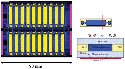
Figure 1 shows a sketch of a possible embodiment and an example of one thermal cycle for PCR. Dimensions are approximately 200*100*2 mm, one cycle is typically one minute.
One of the challenges in bringing these promising products to the market is in designing low cost and at the same time accurate and robust temperature control options. This article shows how numerical modelling may help in the search for potentially interesting designs with a turn-around time that can never be realized by experimentation alone. In particular, numerical results for resistive heating for PCR suitable thermocycler concepts are discussed.
A 20 chamber PCR system
A PCR chip comprising 20 separate PCR chambers on the same substrate was designed, schematically shown in Figure 2. This particular chip is designed for infectious disease detection where up to 20 different DNA samples are needed to identify the disease, and each needs to be individually captured and amplified before it can be detected. In order to realize the temperature control two options exist: either the heaters/sensors are integrated in the disposable, or the heaters/sensors are integrated in the instrument, i.e. the passive heat sink referred to as the cooling chuck. While the first option is by far the most optimal from a temperature control point of view, the prohibitive costs of integrating the heater circuitry in every disposable makes the second option the most viable.
In the final design, each chamber is in itself rather complex, comprising of 9 separate segments (see Figure 6 for details), each with its own set of heating and sensing circuitry. The temperature control is provided by PID (proportional–integral–derivative) circuitry off the glass, and the heaters and sensors are connected through TFT (thin-film transistor) multiplexing elements. It is necessary to deliver a power of up to 10W per chamber in order to achieve the desired heating rates and temperatures, which is near to the maximum that is allowed from an electrical point of view. The heating circuitry uses a pulse width modulation technique to provide heating pulses.
Heater switching times are fast (~5µs), and the chamber temperatures can be switched from level to level in around 1s. Each of the 20 chambers can be driven independently to different temperatures at the same time. Uniformity across each chamber should be maintained to ~1K.
To achieve the required heating rate, power is dissipated by a series of transparent resistors (ITO) located underneath the fluidic areas, sometimes separated by temperature sensors. In an active matrix approach, the individual heaters are addressed line-at-a-time. Thermocycling is achieved by fixing the heater plate to a cooling block through vacuum suction.
Numerical analysis to address the influence of the many parameters
The most important question that we need to answer is: how is the local fluid temperature affected by the aforementioned parameters and are the power levels required to maintain the desired temperature range feasible? Think of the influence of dimensions and material choices for heaters, sensors, cooling chuck, top and bottom layers of cell, walls, heater and guard layout, interfaces, boundary conditions etc. Obviously, numerical analysis is the preferred choice to judge all potential scenarios. To address the question we used a commercially CFD code in conduction-only mode, because early in the research it was established that natural convection did not play any role due to the low Ra number. All simulations are run in transient mode.
The numerical test cell
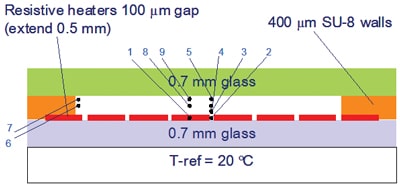
In spite of the preferred choice for heaters deposited on the cooling chuck, the research was started with heaters integrated in the disposable, for reasons of easier testability, to get insight in the dominant heat transfer phenomena. Figure 3 shows a sketch of the test cell.
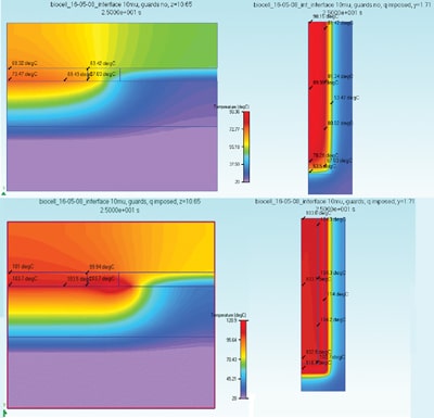
In order to maintain certain required temperature uniformity in space and time the heaters should extend quite a bit beyond the space occupied by the fluid cell resulting in significantly less useful area. Moreover, the total power consumption scales with heater area. Early in the project it became clear that the only feasible way to overcome this problem is by adding a small region, a so-called guard, around the central heater of which the temperature can be controlled in such a way that the heat losses in the lateral direction are minimized. Figure 4 shows embodiments without (top) and with (guards) at the end of the denaturation cycle, and it is clearly seen that at the borders of the cell heat is leaking away to the cold substrate. Left picture at the top: 73.47 in the center, 67.03 in the corner. Right picture: 90.15 in centre (the top in the half-symmetry picture), 67.03 in corner. Left picture at the bottom: 103.7 in the center, 103.7 in the corner. Right picture: 103.8 in center, 103.7 in corner. For sure a significant improvement. What remains is a too large temperature gradient in the vertical direction, of around 4 °C. This can be reduced by changing the top layer from glass to a suitable plastic such as polystyrene. Another remedy against too large gradients caused by the distance between the individual heaters with as a bonus considerable reduction in required power is to use a layer of sapphire (transparent and coupled to a much higher thermal conductivity) on top of the heaters and sensors, which is technologically feasible. The biggest technological hurdle to overcome is to control the thermal resistance of the interface between disposable and chuck.
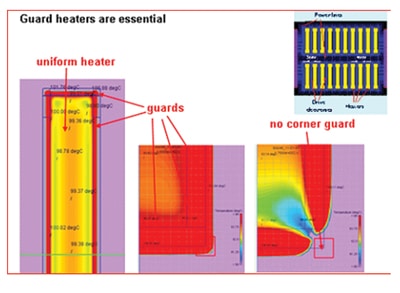
Figure 5 demonstrates clearly what happens if the guard is not completely surrounding the heater. Not powering the small corner guard of 0.5*0.5 mm2 results in a nice visualization of the heat leaking away through the tiny hole in the corner.
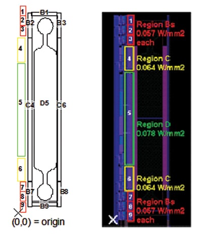
Because the temperatures along the rim of the heater (without the guard) are not everywhere the same, especially near the corners, ideally one guard with only one temperature control will not be optimal, and we have to switch to various zones. The optimal width and length of these zones have been determined using the computer code and resulted in a 9 element layout per cell.
Besides the heater and guards, also the drive electronics dissipate heat and should be taken into account. Figure 6 shows a typical layout, where D5 is the main heater, B and C are the various guard zones, and 1-9 are the drive electronics.
Implementation of the Results in practice
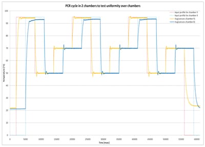
Based on the numerical results a prototype was manufactured. Each heater and sensor pair is run in a closed loop manner by PID controllers. Each heater/sensor pair is accessed once per line time, therefore the field period must be much shorter than the thermal time constant. This is about one second; we have used a field period of 1ms. Every PID controller can have its own parameters (gain factors, control bits, etc.) so every PID controller can be optimized for the heater it must drive. The heater input is set by the PID from the last value read from its temperature sensor. Figure 7 shows closed loop temperature control for two neighboring chambers (on the same row but different column) which were driven out of phase to determine the cross-talk between them. What you see is the temperature input profile and the actual values the sensors provide. Temperature uniformity of both chambers is excellent despite the small (3mm) gap between them. Temperature accuracy is better than 1% under changing ambient temperature conditions [1].
Conclusions
This article describes the numerical analysis and temperature control of Polymerase Chain Reaction (PCR) Lab-on-a-Chip, enabling the amplification of DNA, essentially consisting of a number of fluid cells, to be positioned on a cooling chuck provided with heaters, guards, sensors and control circuitry.
The numerical study incorporated all parameters that were seen as potentially of influence: dimensions and material choices, heater and guard layout, interfaces, boundary conditions etc. Due to space limitation only a few results are presented.
It is argued that numerical analysis is an indispensable tool when it comes to timely and optimal design. It is shown that by taking appropriate measures the required speed (>10 K/s) and temperature uniformity (<1 °C) could be realized, provided the interface resistance between the disposable and the cooling chuck can be controlled to within narrow limits.
Acknowledgments
The authors would like to acknowledge the financial support of the MicroNed program of the Ministry of Economic Affairs of the Netherlands.
References
[1] Fish, D.A., Young, N.D., Collins, P., Ponjee, M.W.G, Hoevenaars, A.A.M., van Beek, W.H.M., Lasance, C.M., Trainor, Gonzales-Rodriguez, F., and Gokgurler, M.H. “A multiplexed thermal array for DNA amplification.” SID Symposium Digest, Vol. 40, pp 471-474, 2009.
[2] Alberts, B., Johnson, A., Lewis, J., Raff, M., Roberts, K., and Walter, P. “Molecular Biology of the Cell.” Garland Science. Chapter 8, pp 508, New York 2002.
[3] El-Ali, J., Perch-Nielsen, I.R., Poulsen, C.R., Bang, D.D., Telleman, P., Wolff, A. “Simulation and experimental validation of a SU-8 based PCR thermocycler chip with integrated heaters and temp sensor.” Sensors and Actuators A. 110, pp 3-20, 2004.


