The meteoric rise in cooling requirements of commercial computer products has been driven by an exponential increase in microprocessor performance over the last decade. The conventional way to cool microprocessors has been to utilize air to carry the heat away from the chip, and reject it to the ambient. Air cooled heat sinks are the most commonly used air-cooling devices with the highest performers incorporating heat pipes or vapor chambers. Such air cooling techniques are inherently limited with respect to their ability to extract heat from semiconductor devices with high heat fluxes as well as carry heat away from server nodes that have high power densities. Thus, the need to cool future high heat load, high heat flux electronics mandates the development of low thermal resistance and highly energy efficient thermal management techniques, such as liquid cooling using cold plate devices.
Liquid cooling of electronics is not a new technology. The need to further increase packaging density and reduce signal delay between communicating circuits led to the development of multi-chip modules beginning in the late 1970s. The heat flux associated with bipolar circuit technologies steadily increased from the very beginning and really took off in the 1980s [1]. IBM had determined that the most effective way to manage chip temperatures in these systems was through the use of indirect water-cooling [2]. Several other mainframe manufacturers also came to the same conclusion [3-7]. The decision to switch from bipolar to Complementary Metal Oxide Semiconductor (CMOS) based circuit technology in the early 1990s led to a significant reduction in power dissipation and a return to totally air-cooled machines. However, this was but a brief respite as power and packaging density rapidly increased, matching then exceeding the performance of the earlier bipolar machines. These increased packaging densities and power levels have resulted in unprecedented cooling demands at the package, system and data center levels necessitating a return to water-cooling [1, 8-9].
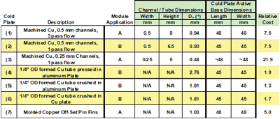
This article focuses on some of the design trade-offs associated with the processor cold plate. Two general types of cold plates are considered: a relatively high performance, high cost machined copper cold plate and a relatively low performance, low cost copper tube embedded in aluminum cold plate. Thermal performance in the context of the product application is also addressed.
Cold Plate Descriptions
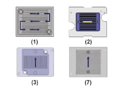
A summary of the cold plates under consideration in this exercise can be found in Table 1. Cold plates (1), (2), and (3) are copper blocks with rectangular channels for the water to flow through. Cold plates (1) and (2) have 0.5 mm wide channels while cold plate (3) has 0.25 mm wide channels. Cold plate (1) is a 3-pass flow design in that flow passes sequentially through 3 groupings of channels (Figure 1); each with a third of the total number of channels. By contrast, cold plates (2) and (3) are 1-pass flow designs; water flows through all the channels in parallel. Cold plates (2) and (3) are shown in plan view (transparent to show channels and fins) in Figure 1. Also depicted in Figure 1 is cold plate (7) with pin fin geometry.
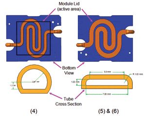
Cold plates (4), (5), and (6) are comprised of 6.35mm (¼”) outside diameter (OD) copper tubes embedded in an aluminum or copper plate. Cold plate (4) has its tubes flattened slightly to provide favorable thermal contact with the module lid. The formed tube cross section can be seen in Figure 2. The tubes in cold plates (5) and (6) are flattened to a greater degree for increased thermal performance: a greater fraction of the module lid area is in contact with the copper tubes along with a reduced hydraulic diameter for increased convective heat transfer. The price of this enhancement is increased pressure drop. Note, however, how inexpensive the copper tube cold plates (4), (5), and (6) are in comparison to the machined copper cold plates (1), (2), (3), and (7). The 0.25 mm channel cold plate (3) is by far the most expensive as it required wire electrical discharge machining (EDM) to form the channels.
Analysis Results and Discussion
Conjugate thermal analyses were performed on the cold plates described in the previous section using a commercially available computational fluid dynamics code [11]. In order to objectively compare cold plate thermal performance, a uniform heat flux boundary condition was applied to each cold plate’s active cooling area, which is defined for the purposes of this comparison as the cold plate area which is conduction coupled to the module lid by a thermal interface material (TIM). The cold plate thermal performance is defined by a total unit thermal resistance (mm2 C/W),
where base is the average temperature of the cold plate base active cooling area (oC), Tin is the water inlet temperature (oC), and q” is the heat flux applied to the cold plate base active cooling area. R”total, which captures both convective and advective heat transfer behavior, does not completely capture the true nature of the cold plate’s thermal performance. The copper tube cold plates, having larger characteristic dimensions, rely on transitional or turbulent flows to achieve heat transfer performance while the machined cold plates with smaller characteristic dimensions rely on large wetted areas to achieve performance. Since the two types of cold plates compared in this study have very different pressure drop characteristics, implementations of the two types would necessarily require disparate flow rates (high flow rates for the formed tubes, and much lower flow rates for the small machined channels). The thermal resistance calculated in equation 1 includes the temperature rise of the fluid within the cold plate implicitly. Consider a micro-scale channeled cold plate, with extremely enhanced area but a high pressure drop and a pressed tube cold plate, both having equivalent thermal performance at the module level. For this to be true, the microchannel cold plate would have to be at a low flow rate, and the pressed tube at a relatively high flow rate; clearly most of the thermal resistance of the microchannel in this case is temperature rise of the fluid, whereas in the pressed tube the resistance is dominated by the heat transfer coefficient on the tube walls and the available area. To better observe this differing behavior, we also compare the cold plates by their convective performance only, and so define a convective unit thermal resistance (mm2 C/W),
where is the water mass flow rate (kg/s) and Cp is the water specific heat (J/kgK).
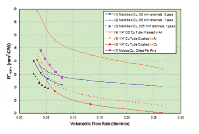
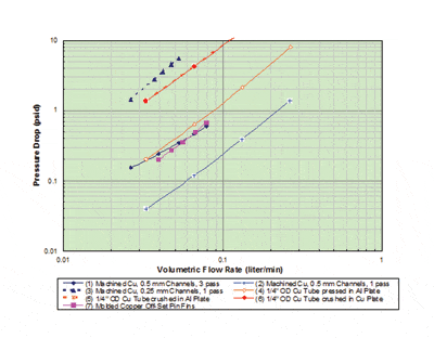
The convective performance of the cold plates is depicted in the graph in Figure 3. The machined (plus pin fin) cold plates achieve a high level of performance with relatively little flow. The slightly formed copper tube cold plate (4) performed the worst with comparable behavior to the machined cold plates only at much higher flows. The crushed tube (5) and (6) fa
ired much better although the resulting pressure drop, seen in Figure 4, is an order of magnitude higher than that associated with the 0.5 mm channel cold plates (1) and (2) or the slightly formed copper tube cold plate (4).
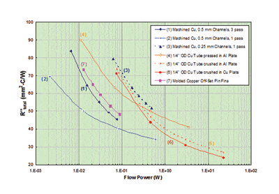
It is also useful to compare the cold plates using the total resistance as a function of flow power (Figure 5) to capture the convective and advective resistance as well as the pumping power cost associated with the varying flow rates and pressure drops inherent to these different geometries. Flow power (W) is defined as,
where DP is pressure drop (Pa) and is volumetric flow rate (m3/s). Clearly, the higher pressure drop, higher flow cold plates required much higher flow power (2 orders of magnitude in some cases).
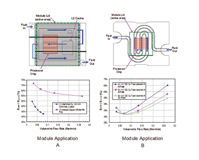
Finally, consideration must also be made to how the cold plate performs in the actual product application. Several of the cold plates in this study were incorporated into two different product module applications (depicted in Figure 6). The cold plate thermal resistance in the context of the module application is determined by
where Tpr is a point reference temperature on the cold plate base corresponding to the x-y center of the processor and q is the total processor heat load. This thermal resistance is compared to the thermal resistance resulting from the uniform heat flux boundary condition previously discussed and is defined as
where Amod is the module lid (active) area. By graphing in Figure 6 the ratio of these resistances, (RUHF / Rprod), it can be seen that the actual performance can be considerably less (by a factor of 2) than the idealized uniform heat flux case; the RUHF / Rprodmetric as shown represents an efficiency, where values less than 100% indicate to what extent the final design under-performs the idealized uniform heat flux case. The magnitude and variation with flow will vary with cold plate type and module application. One interesting feature of these packages is that as the overall thermal resistance of the package decreases, less spreading is taking place
in the lid and cold plate base; conversely, as the cold plate resistance increases, the heat flux from the lid becomes more uniform. In the case of a laminar flow cold plate, such as (1) and (7), the heat transfer coefficient between the channel walls and the coolant is not a function of flow rate; only the advective resistance is affected by increasing flow, resulting in a characteristic RUHF/Rprod that decreases as flow increases. Alternatively, a cold plate with a larger hydraulic diameter and higher flow rates can be in transitional or turbulent flow, such as cold plates (4), (5), and (6); with transitional and turbulent flows the heat transfer coefficient between the tube walls and the coolant increases with increased flow rate, lowering the resistance of the path from the lid through the interface to the cold plate base and into the side walls of the tube.
Conclusions
Two differing cold plate technologies for cooling processor modules have been compared. The following observations and conclusions can be drawn from the analysis results presented herein:
1. Cold plate thermal resistance performance, whether inclusive or exclusive of advective resistance, does not translate to a better design (i.e. one that most closely satisfies all of the design constraints of pressure drop, cost, and thermal performance). A more costly cold plate does not guarantee a better design.
2. The entire system design must be taken into account when designing / specifying a cold plate. Choices at the system level can elevate design requirements on the cold plate (i.e. allow for a lower performance / lower cost design). Specifically, given a thermal resistance target that can be met with a low flow, expensive, high pressure drop cold plate or a high flow, inexpensive, low pressure drop alternative, the coolant routing within the system (parallel versus serial paths, for example) and the available pump performance are key to the cold plate selection.
3. Cold plate thermal resistance based on a uniform heat flux (UHF) boundary condition can not be applied directly to a product application specification. Performance in the product application can be very different from what the UHF resistance would suggest.
References
[1] Ellsworth, Jr., M.J., Campbell, L.A., Simons, R.E., Iyengar, M.K., Schmidt, R.R., Chu, R.C., “The Evolution of Water Cooling for IBM Large Server Systems: Back to the Future,” Proceedings of the 2008 ITherm Conference, Orlando, FL, USA, May 28-31.
[2] Simons. R.E., ”The Evolution of IBM High Performance Cooling Technology,” Proceedings of the Eleventh Annual IEEE Semiconductor Thermal Measurement and Management Symposium, 1995, pp. 102-112.
[3] Kaneko, K., Seyama, K., and Suzuki, M. “LSI Packaging and Cooling Technologies for Fujitsu VP2000 Series,” Fujitsu Scientific & Technology Journal, v. 41, no. 1, 1990, pp. 12-19.
[4] Kaneko, K., Kuwabara, K., Kikuchi, S. and Kano, T. “Hardware Technology for Fujitsu VP2000 Series,” Fujitsu Scientific & Technology Journal, v. 37, no. 2, 1991, pp. 158-168.
[5.] Kobayashi, F., Watanabe, Y., Yamamoto, M., Anzai, A., Takahashi, A.,Daikoku, T., Fujita, T., “Hardware Technology for Hitachi M-880 Processor Group,” Proceedings of the 41st Electronic Components and Technology Conference, 1991, pp. 693-703.
[6.] Watari, T., Murano, H.,” Packaging Technology for the NEC SX Supercomputer,” IEEE Transactions on Components, Hybrids, and Manufacturing Technology, Volume 8, Issue 4, 1985, pp.462 – 467
[7.] Murano, H., Watari, T., “Packaging technology for the NEC SX-3 Supercomputers,” IEEE Transactions on Components, Hybrids, and Manufacturing Technology, Volume 15, Issue 4, 1992, pp. 411 – 417.
[8.] Ellsworth, Jr., M.J., Goth, G.F., Zoodsma, R.J., Arvelo, A., Campbell, L.A., Anderl, W.J., “An Overview of the IBM Power 775 Supercomputer Water Cooling System,” Proceedings of the ASME 2011 Pacific Rim Technical Conference & Exposition on Packaging and Integration of Electronic and Photonic Systems (InterPACK 2011), Portland, Oregon, USA, July 6-8.
[9.] Wei, J., “Hybrid Cooling Technology for Large-Scale Computing Systems – From Back to the Future,” Proceedings of InterPACK 2011, Portland, Oregon, USA, July 6-8.
[10.] Sahan, R.A., Rahima, M.K., Xia, A., and Pang, YF, “Advanced Liquid Cooling Technology Evaluation for High Powered CPUs and GPUs,” Proceedings of InterPACK 2011, Portland, Oregon, USA, July 6-8.
[11.] Fluent, Distributed by ANSYS, Inc.; Southpointe, 275 Technology Drive, Canonsburg, PA, 15317, www.ANSYS.com l


